User:MinorProphet/Draft subpages/WW2 Maybach gearboxes
| This is not a Wikipedia article: It is an individual user's work-in-progress page, and may be incomplete and/or unreliable. For guidance on developing this draft, see Wikipedia:So you made a userspace draft. Find sources: Google (books · news · scholar · free images · WP refs) · FENS · JSTOR · TWL |
This is a short list (and long explanation) of the semi-automatic, pre-selector gearboxes designed by Maybach and made under contract by ZF, fitted in German tanks and half-tracks before and during World War II. This article was created as an adjunct to List of WWII Maybach engines and User:MinorProphet/Draft subpages/WW2 ZF gearboxes.
In theory™ the list itself should be relatively short,[a] since there were only five production-series models of this type, fitted to the Sd.Kfz. 10 and its armoured derivative the 250; and to various models of the Panzer I, Panzer II, Panzer III, Tiger I, and II and derivatives. Indeed, what a lot of fuss for five production and five test gearboxes, total 10 models.
As far as I am aware (hah!), only the gearbox fitted to the Panzer III up to mid-1939 suffered from major problems, and they appear to be a combination of design faults by Maybach as well as manufacturing faults by the main sub-contractor, ZF. The rest appear to have been relatively well-behaved.
All the gearboxes discussed here are of the semi-automatic, pre-selector type.
Pages from the Commercial Motor edit
OKKK
Maybach#1909–1940: Early history says this:
- "Maybach had a British subsidiary, Maybach Gears Ltd, that specialised in gearboxes. In 1938, in conjunction with Dr Henry Merritt, they produced a gearbox and steering system – the 'Merritt-Maybach' – for the abortive Nuffield A.16E1 Cruiser tank design.[1]"
So, I happen to have this book, and
C:\_Mikey D's Old Documents\Downloads\__Military\_Tiger_Tank_Haynes_manual\11.jpg
is the page.
But is it the same gearbox? Check the specs for whatever was used in the Tiger and the Nuffield - 7, 8, 10 gears??
C:\_Mikey D's Old Documents\Downloads\__Military\Tank_Steering_Systems.pdf says 7.
Next... MinorProphet (talk) 21:16, 14 December 2023 (UTC)
Haynes: "Workshop Manual: Tiger Tank Panzerkampfwagen VI Ausf. E (Sd.Kfz. 181)"
...patent No. 341,379, by the Maybach-Motorenban GeselLschaft
A Six-speed Gear 17th February 1931, Page 80 ...patent No. 341,379, by the Maybach-Motorenban GeselLschaft,
"..the Vomag six-wheeler, for example, has a 12-cylindered Maybach unit of 150 b.h.p., the capacity being close upon eight litres," Pointers from the Berlin Show 24th February 1931, Page 56
A London Bus Trial of the Maybach Gearbox 10th May 1932, Page 38
New Maybach Multi-speed Preselective Gearbox 14th August 1936, Page 27
"MAYBACH GEARS, LTD. 311 This company will show its preseiective multi speed gearbox which, with four pairs of constant-mesh gears, provides seven forward speeds. the seventh gear being overdrive and the sixth direct. Its weight is no more than a normal four-speed box, with a total height of only 10 1/4? ins. The gear control is vacuum-operated. Lincoln House, 296-302, High Holborn, London, W.C.1. [2] 29th October 1937
In 1935 the sole agent in Britain for Maybach was Ernst Schneider, who hoped to market/sell a six-speed automatic gearbox for tanks. Maybach Gears Ltd. was incorporated in February 1936 with capital of £10,000. The Managing Director (Geschäftsführer) was Jean Raebel, and a licence to make Maybach gearboxes for GB, Ireland, colonies and Dominions was agreed in March 1936.[2] In November 1936 Leyland Motors acquired a sub-licence to make the gearboxes, and Dennis Bros. in February 1937.[3] However, the worsening political situation meant that by December 1938 the Germans were having serious doubts, and in June 1939 the OKH told Maybach-Motoren to rescind the licences.[4]
Raebel became quite important within M-M, see eg pp. 205ff, section 11.3 "Nachbau", all about setting up a clone factory in Lochbrücke near Friedrichshafen, also the Kommission sent to the front to examine the problem of spare parts etc.
Terminology edit
Gearbox/transmission edit
This article deals only with the shift-speed gearboxes (also 'transmissions') of the constant-mesh, semi-automatic, pre-selector type with synchromesh, designed by Maybach AG of Friedrichshafen and made by ZF and its licensed sub-contractors before and during World War II, and installed in German military vehicles up to 1945. None of these are of the manual gearbox (German: Schaltgetriebe) type.
This article generally uses the term 'gearbox' to refer to a single speed-shift mechanism (which may or may not incorporate a main clutch), connected to the engine by a drive shaft (Gelenkwelle). In half tracks etc. this main speed-shift gearbox is often coupled with a second 2-speed reduction (hi-lo) gearbox, NO!!! either externally, or integrated within the main gearcase. NO AGAIN!!! There are various possible configurations.
Tanks:
  Engine at rear - drive shaft - clutch + gearbox by driver - final drives at front (Pz IV)
  Engine at rear + clutch - drive shaft - gearbox by driver - final drives (Pz III H+)

Half-tracks:
  Engine in front + clutch - gearbox + hi-lo - drive shaft - final drives behind driver
  Engine in front - etc.
Although the term is not used in the following sense in this article, 'transmission' in both British and US English can be used to refer to the entire mechanism by which power is transmitted from the engine to the road wheels (or drive sprockets in a tank or half-track). This may include a drive shaft (or propellor shaft, commonly called a 'prop shaft'), a clutch, the main shift-speed gearbox itself, further speed reduction gearboxes (popularly called hi-lo boxes), differentials, steering gear (Lenkgetriebe), braking systems, etc. None of these are discussed in any detail in this article, except for the following section.
Clutches edit
Various clutch (Kupplung) mechanisms were used, often incorporated within the main gearcase. These may include: dog clutches (Klauen??) or simply 'dogs', which engage specific meshing gear pairs on a gear shaft (German: Getriebwelle) to construct a desired gear ratio; accelerator and braking clutches (either of the cone or multi-plate type) which speed up or retard specific gear shafts (Getriebwelle) to assist a noiseless synchromesh (Synchrongetriebe) operation, often just called 'synchro':[b] and a multi-plate main clutch (Hauptkupplung), either of the wet or dry clutch type to engage or disengage the entire gearbox from the engine. These are all discussed further in the article.
Background edit
Soden transmission edit
Soden transmission section cut and pasted to User:MinorProphet/Draft subpages/WW2 ZF gearboxes#Soden transmission (2nd version), where it belongs.
Basic ASCII diagrams for Variorex VG 10 2 128 edit
See also User:MinorProphet/Draft subpages/WW2 ZF gearboxes#Soden transmission et seq.
The pins (one per gear) are held in place - by spring pressure when selected. When the clutch is depressed, a mechanically opened valve allows a vacuum into the pneumatic system. All the pistons are retracted by vacuum (i fink); the drilled control shaft rotates into its pre-determined position; the relevant pin or pins locate into the relevant hole in the drilled shaft by spring pressure; and selector forks attached to the pistons slide one or more dog clutches, to engage the next pre-selected gear train. Releasing the clutch pedal after about one second re-enages the clutch, and restores power to the final drive. A locking mechanism holds the main selector shaft in place until the next gear is pre-selected by the shift lever. Or something.
See again Kedoki, but he's talking about the SRG 32 8 145 in the Panzer III.
   | |= O Pin (left) and drilled selector rotor shaft (right)
  _|_|__________
 |______________| Pneumatic valve and piston. → Spring pressure to engage
   | |                                        ← Disengaged by vacuum
    \ \    Selector fork to slide dog clutch
     \ \

  Fig. X. Side view of selector valves in Variorex VG 102 128
Further development of semi-automatic gearboxes edit

I still haven't quite worked out how the vacuum was achieved. The Leichttraktor apparently used a de:Pallas Autovac-style autovacuum device,[5], but since the Soden transmission was entirely mechanical in operation more thought is needed. The Mercedes-Benz-Maybach 3x2 gearbox in the WO 7 used the partial vacuum in the inlet manifold:
- "In 1930/1931 Mercedes announced a sports car with a 7.7 litre supercharged straight-eight, with a special Mercedes-Benz-Maybach multiple-range gearbox giving six speeds. The change is effected by the employment of the partial vacuum in the inlet manifold, controlled from the steering wheel." Possibly the Mercedes-Benz 770 or Großer Mercedes."[6]
- "The transmission represented a special feature, as an overdrive [on all three gears] could also be selected in addition to the usual three forward gears [fore-and-aft gear lever mounted directly on the gearbox], making a total of six forward gears available. The overdrive was preselected via a lever on the steering wheel, and activated by briefly decelerating without pressing the clutch. The same method was used for shifting down. Throughout the entire construction period the ‘Super Mercedes’ of model series W 07 had the two final-drive ratios i = 4.5 and i = 4.9 at its disposal."[7]
See also driving tips from a 1932 Mercedes manual.[8]
Stunning pic of polished aluminium gearbox:[9]
General operation of Maybach gearboxes edit
The driver pre-selects a gear with a small lever in a quadrant, attached either to the gearbox on the driver's rh side, or on the steering wheel column. This determines the next gear ratio to be engaged. Nothing obvious happens until the clutch pedal is depressed for around one second and then released. The gears are changed smoothly with no further action by the driver. A second direction lever controls forward and reverse, with neutral in the middle.
Overview of Maybach gearbox types edit
See User talk:MinorProphet/Draft subpages/WW2 Maybach gearboxes#Nomenclature... for earlier research...
Oi!!! Merge with #Summary of Maybach semi-auto gearbox numbering schemes (finally) below!
Maybach used a combination of letters and numbers to identify their gearboxes: e.g. VG 10 2 128 or OG 40 12 16.[c]
A) The initial letters indicate the type of internal semi-automatic gear-shifting mechanism:
- SRG=Schaltreglergetriebe ('shift control transmission');
- VG= Variorex-Getriebe;
- OG = Olvar-Getriebe.
B) These letters are followed by a 3-part model numbering scheme indicating:
- the power (Leistung) and
- the maximum torque (Maximaldrehmoment, abbr. Md.) of the engine which the transmission was originally designed for; and
- the total gear reduction ratio (Gesamtsprung) of the gearbox, designated in formulas as (i).
B1) These numbers represent:
- 1st numbers = 100s and 10s components of engine power in PS. Example: 14 = 140 PS as in SRG 14 4 79
- 2nd numbers = 100s and 10s components of torque in mkg. Example: 8 = 80 mkg, as in SRG 32 8 145
- 3rd numbers = total gearbox reduction ratio (i), leaving out any decimal point (decimal comma in German) Example: 128 = i=1:12.8, as in VG 10 2 128.
In both contemporary sources and recent historical works these 5- or 6-figure numbers are written in various unmeaningful combinations (e.g. 'SRG 328145' and 'SRG 328 145'); in this article they are shown for clarity as three separate groups, e.g. SRG 32 8 145, to align with the numbering of the later OG series.
Main sources for the above: Spielberger [& Doyle] (1998), Panzerkampfwagen Tiger und seine Abarten, 6th edition (in German), p. 18; and Spielberger (1994), Sturmgeschütze: Entwicklung und Fertigung der sPak, p. 37.
However, these numbers relate to the engine for which the gearbox was originally designed. Spielberger Tiger & Abarten p. 18 says that the Olvar OG 40 12 16 was initially developed for an engine of 400 PS output, approx. 120 mkp, and a reduction ratio of 1:16. This transmission was eventually fitted in the all the Tigers, along with the HL230 which developed 700 PS @3,000 rpm and 185 mkg @2,100 rpm.(Spielberger, Panther and variants, p. 235) An accurate reflection of this engine's capabilities would result in a theoretical OG 70 18 16 [assuming the total reduction ratio remains the same]. MinorProphet (talk) 11:10, 17 July 2022 (UTC)
Similarly, late experimental models of the Panzer II n.A (neue Art) Ausf. H & M (VK 9.03), had a "strengthened" VG 15 3 19 (Table 2 below). This was fitted with an HL66 P developing 180 PS @3,200, and 46 mkp @2,000 (J&D, PzTr 2-2, p. 2-2-12). Its theoretical numbering should therefore be a VG 18 4 319 (assuming the reduction ratio wasn't changed - hah!)
Furthermore, since they omit the 1s component, the figures for power and torque are necessarily approximate: thus the 14 figure in the SRG 14 4 79 could reflect any value from 140 to 149 PS. But since they relate to the power of the engine for which the gearbox was originally designed, and not necessarily what it was finally attached to, the figures may be essentially meaningless and only serve to distinguish one gearbox from another and don't necessarily reflect its true capabilities.
The numbering of some later transmissions may more closely reflect the capabilities of the relevant engine: eg the OG 55 11 77, used in the VK 16.02 'Leopard', with a (fuel-injected?) HL157 P which developed 550 PS @3,500 (torque unknown, could be 110 mkg, since the HL230 made 185 mkg). A reduction ratio of 1:7.7 seems a little low, but with the trend for gearboxes with fewer gears, it could be possible.

SRG series edit
Overview edit
SRG transmissions were fitted to certain models of the Panzer I, Panzer II Ausf. D & E , and the first main production models of the Panzer III. The SRG 32 8 145 installed in the Panzer III Ausf. E-G up to mid 1939 was pretty much a disaster: A) because it was rushed into production without being fully tested: B) partially because of lack of precision and faulty assembly of the complex and intricate mechanism at outsourced factories including ZF; and C) partly because of original design faults by Maybach. These had become apparent by March 1940. Problems due to faulty assembly were usually corrected in the field, with the help of a Maybach technician who would make the new parts; and the transmissions suffering from design faults were returned to the maker, Henschel?(J&D, PZ Tr 3-2, pp. 36-38) By 1941 the faults had been ironed out, and the SRG 32 8 145 performed relatively well in Russia and North Africa.
The SRG 32 8 145 eventually used a complex combination of inter-dependent mechanical, pneumatic and hydraulic mechanisms to pre-select and shift the gears, assisted by a § Gasgeber vacuum-operated membrane valve to rev the engine. Within the transmission casing, vacuum-operated valves/pistons shifted the dog clutches, and hydraulic accelerator and braking clutches effected synchronised gear changes.(ref. Kedoki.) It's all very complex. In fact so complex that it took at least four years until c1941 to sort out.(Ref needed, probably a Panzer III book.) In consequence Maybach completely revised their gearbox model numbering scheme in 1939. The name 'SRG' was unceremoniously dropped, and the 'Variorex' name ('VG') was substituted.[10] Thus the term 'Variorex' is used to refer to the previously-named SRG series, even in contemporary reports, leading to confusion with later VG types.
NB! This is a very typical example of putting technology that hasn't been fully tested into series production. To develop a brand new engine or transmission takes several years, at least.
Technical explanations (in Russian) edit
Machine translation works well with all the following lengthy and highly detailed explanations:
- Part 1: Kedoki. "О крайней упоротости Pz.III ausf.E-G. Почему Pz.III ausf.E-G упороты" [Flaws in the Panzer III Ausf. E-G]. Kedoki (in Russian). Archived from the original on 19 February 2018. Retrieved 21 April 2018. (Russian website, but machine translation is not too bad these days).
- Part 2: The extreme stubbornness of the Pz.III ausf.E-G. How the Pz.III ausf.E-G stubs (?)
- Part 3: The extreme stubbornness of the Pz.III ausf.E-G. What came of it
- Problems of production and reliability of the Pz.III ausf.E-G and their overcoming or about Ivan's extreme obstinacy NB There is little about the gearbox in this post, it's mostly a lively response to another blogger with alternative views.
- Driving the Tiger. Tank device and control principles. Part one: steering mechanism (Outside the scope of this article)
Installation in Panzer III Ausf. E, F, G edit
Good-ish pic of Maybach SRG gearbox on p. 58 of AFV Interiors of WW2 §§§ This actually a well-written and clear explanation of the insides of lots of German tanks. Sadly no refs, but lots of it is simply description of the photos. On pp 68-9 he states the difference between HL120 TRMs installed in Panzer III and IV: the exhausts curve upward at one end on the Pz III; on the Pz IV they pass straight through the rear wall.
...plus stuf about other tanks: edit
Good pix of the rear end of ZF AK 7-200, pp 146-7. Pic on p. 158 of the AK 7-200, saying it was also a pre-selector - you can see the typical round selector cover at top right. "The syncromesh only works when the engine rpm is between 2000 and 2300, or when changing down at a lower rpm." Says the steering system was far too weak to cope with the torque (200 mkp) of the engine and gearbox. "The double-spur reduction gears and their mounts were far too small and weak to handle the torque they controlled. This was because the Germans did not have sufficient numbers of milling machines to make the proper gearing,[f] and as a result, many Panthers were lost when these gears, or their mounts, failed." Really? Sounds possible (AFV Interiors of WW2, pp. 153-4) The big tubes leading to the rear of the gearbox aren't for water (as I thought) but air ducts which removed heat and smell into into the engine compartment.
Aha! Major causes of engine fires in the Panthers etc.:
1) "Interestingly, the original amphibious design of the tank's engine compartment was to provide one of its worst problems- engine fires. The restricted air flow in the engine compartment [the originally specified Schnorkel apparatus was later removed, but cooling space in the engine compartment was not improved] allowed fumes to accumulate, primarily due to leaky hose connections and fuel tank seam failures. Any hot components or sparks would then cause catastrophic engine fires, disabling and often destroying numbers of Panthers before they reached the battle field." (AFV Interiors of WW2, p. 160)
2) "Although most of these problems had been resolved by the time the Jagdpanther went to war, there were still numerous engine fires reported, some caused by leaky cylinder head gaskets allowing oil to drip on the exhaust headers. For some reason, German gasket technology was not well developed and it would affect both airplane and automotive designs."
"The predominate color of the engine components (block and cylinder covers) is gloss black, a favorite at the Maybach assembly plant, but much of the additional equipment from subcontractors can be black, metallic or even red, as was the case with some of the electric starters from Bosch." (AFV Interiors of WW2, p. 161)
Oh dear... edit
Oh dear, the SRG 32 8 145.[g] Fancy going to war with the transmission of your most numerous medium tank proving to be very unreliable? The Germans did. (Go to war, I mean. I imagine they they didn't fancy the prospect.) Combat reports, please... probably Panzer divisions 1,2,4...?
NB Not every gearbox exhibited signs of failure. Those that had been badly assembled tended to fail by around 800 km, and were corrected.(J&D, Pz Tr 3-2-36 to 38) In fact, the combat reports just cited for 1st and 2nd Pz Regiments give the actual chassis numbers, which can be shown to be Es and Fs, according to this table:
Total Ausf. E, F, & G made: chassis nos. (Fahrgestell Nr.) || What do J&D say in Pz Tr 23?
- E: 60401 to 60496 - total 95 (Pz Tr 3-2-5) || yes, plus 45 Pz.Bef.Wg (J&D 23-32)
- F: 61001 to 61636 - total 635 (Pz Tr 3-2-16) || No, only 435 (not all chassis numbers were used)
- G: 65001 to 65950 - total 950 (Pz Tr 3-2-44) || No, 594+6 (ditto)
- Total Panzer III Ausf. E, F, & G made, according to (J&D Pz Tr 3-2, pp 5, 16, 44): 1,680
- Total Panzer III Ausf. E, F, & G made, according to (J&D Pz Tr 23, p. 23-32): 680 vehicles.
- Total of earlier pre-series: A - 10; B - 10+5; C - 15; D - 30, + 30 Pz.Bef.Wg. = total 70 + 30 command tanks. (J&D Pz Tr 23, p. 23-32) This matches exactly with the figures quoted in (Spielberger, Panzer III & variants pp. 140–143)
- But these figures STILL don't add up - try again, fool!
So this figure of 680 tanks now makes sense of the total number of Maybach SRG gearboxes sub-contracted and made by ZF, namely 1305 - basically ZF had to make made double the number of gearboxes than tanks, which means an average of 2 per tank, which means if they were all used, then almost every single Maybach SRG gearbox could have been replaced (in theory). Or some tanks at the start of the run of Ausf. E may have had several gearboxes... I fondly imagine that the changes made in the field to the first gearboxes with the help of Maybach technicians might have been incorporated into the later production runs...
Hmm... Possibly not - all the 40-plus Panzer IIIs left in Norway when Panzer-Division Norway was transferred to the Eastern front had those "unreliable transmissions"... User:MinorProphet/Draft subpages/Panzer Artillery Regiments, 25th Panzer Div.
In about 1937 Ernest Kniepkamp [Short biographical sketch of Kniepkamp in Spielberger, Panther tank and variants p. 230] had requested a 10-speed box for the latest Panzer IIIs (after the Versuchs series of Ausf. A–D), and Insp. 6 requested a semi-automatic transmission for inexperienced drivers & to reduce general driver fatigue.[11]
Approximate numbers of pre-series vehicles made: - Ausf. A, 10; B, 15; C, 15; D, 30, total c70.(Spielberger Panzer III and variants, pp. 140–143)
However, even by mid-1938, Maybach's failure to deliver a single reliable working example of its new transmission was causing major delays in the first quantity series production run of the Panzer III, the Ausf. E. In fact, the whole project was a year behind schedule, and assembly of even the very first of ninety-six chassis by Daimler-Benz hadn't even begun.(Pz Tr. p 3-2-12) This batch of E-Gs was the 6. Serie Z.W.
Maybach had outsourced/licensed production to ZF. (Pz Tr. p 3-2-11) ZF reported they made 23 SRG 32 8 145 in 1938, 223 in 1939, 1015 in 1940, and 44 in 1941 (Panzer Tracts 3-02, Panzer III - Ausf. E, F, G. H, p. 3-2-11) Total: 1305 units produced.
Total PZ IIIs Ausf. with 3.7cm Kw.K gun manufactured: 603 (Pz Tr. p 3-2-12) This was all the E-F output, plus a hundred or so of Ausf. Gs (NB all the Ausf. H had the ZF SSG 77 and the 5cm KwK)
By early 1939, almost no complete tanks had been delivered, production had ground to a halt with no working transmissions available. Despite all the modifications, including the Hochtreiber or accelerator clutch, it still wasn't working by the autumn of 1939. and it was decided to install the SSG 76. Even so, "the Waffenamnt was forced to deliver over 1400 Z.W. (''Zugkraftwagen'') with the Maybach transmission because a different transmission couldn't be acquired fast enough." {Jentz & Doyle. Panzer Tracts 3-2, pp. 13-14)
- Well - NB! Panzer Tracts no. 23 details all the known Panzers ever delivered, with chassis numbers and all: in the introduction J&D accept they made numerous errors in their earlier volumes, because they were not fully aware of the various complex paper-based procedures which specified the delivery/acceptance of every single tank with its chassis number (Fahhrgestell Nr.). Thus there were only 680 Panzer III Ausf. E, F, G ever made, according to Panzer Tracts 23, Panzer Production, p. 23-32.
J&D, in Panzer Tracts 3-2, detail the known delivery of a handful of early PZ III Ausf. Es to individual Panzer regiments by DB and Henschel: 2nd Pz Regiment, 2nd Panzer Division by late March 1940; 15th Pz Rgt, (formed September 1940 as part of new 15th Panzer Division, sent to Libya in 1941 as part of Afrika Korps); 33rd Pz Rgt (9th Panzer Division) by June 1940. MIAG completed 10 Ausf. Fs from September-December 1939, and 40 Ausf. Fs from April to June 1940.(J&D, Panzer Tracts 3-2, p. 3-2-18) Probably see Pz Tr 23 as well... yep, 60 altogether (Pz Tr 23, p. 23-32)
Reports with details of technical failures from 1st and 2nd Pz Regts (1st and 2nd Pz Div i fink) from March 1940 after the Polish Campaign (Panzer Tracts 3-2, p. 3-2 pp.36-8). Pz III Ausf. G mostly had the 5cm KwK, (up to 160 made with the 3.7 cm gun), 878 Ausf. Gs made (Panzer Tracts 3-2, p. 3-2-46)
- NB! Pz Tr 23 corrects this figure, stating only 594+6 as the total. J&D may have counted the total chassis numbers allocated to this batch, but not all chassis were completed. Maybe a previous order for 800 was reduced to 600 somewhere?
The Ausf. H was the 7.Serie Z.W. The ZF SSG 77 gearbox was to be ready for delivery in April 1940.(Panzer Tracts 3-2, p. 3-2-68, -71) 500 built (chassis nos. 66001 to 66500). (Pz Tr 3-2-84)
- NB!! Actual numbers were 286 - I (or others) may have assumed (fatal flaw!) that all allocated chassis numbers were actually assembled: but they weren't - as Jentz and Doyle, Panzer Tracts 23, Panzer Production from 1933 to 1945, p. 23-32 shows.
Many of the gearbox faults experienced in the field were blamed on careless or faulty assembly work at the (outsourced) factories. (Which?? - ZF?) By 1941 the assembly problems had been ironed out, and gave reliable service in both North Africa and Russia,(Panzer Tracts 3-2, p. 3-2-44) but as a result of the delays the ZF's SSG 77 was fitted to the Ausf. H and onwards, from c.September 1940.
Gr. Panzerbefehlswagen (Sd.Kfz. 266–268) edit
These were assigned to the signals detachments (Nachtrichtenzug) of Panzer-abteilungs, -regiments, and -brigades, and later to divisions.(Pz Tr 3-4, p. 3-4-2) All the Panzer IIIs had the bulky frame aerial fitted on the rear deck, plus an assortment of pole aerials up to 9 metres.
According to Pz Tr 3-4, there were 45 Ausf. E produced of the Pz. III radio-equipped command tank, chassis nos. 60501 to 60545, from July 1939 to February 1940.(Pz Tr 3-4, p. 3-4-54) J&D don't give any stats at all for the Ausf. E, but it seems very likely that they were fitted with the Maybach gearbox like the rest of the Ausf. E-G. Until May 1941 they were known as Pz.Bef.Wg. III Ausf. B.(Pz Tr 3-4, p. 3-4-2) The Es had the HL120 TR engine. The type of extra command radios fitted determined the Sd.Kfz. number (from List of Sd.Kfz. designations):
- Sd.Kfz. 266: Panzer III command tanks with FuG 6 and FuG 2 radios
- Sd.Kfz. 267: Panzer III command tanks with FuG 6 and FuG 8 radios (also Panthers and Tiger Is)
- Sd.Kfz. 268: Panzer III command tanks with FuG 6 and FuG 7 radios (also Panthers and Tiger Is)
Wireless Communications of the German Army in World War II says that almost all panzers had the FuG 5 (10 Watts VHF transceiver, 125 channels) installed as standard, for short-range tank-to-tank comms within platoons and companies.
- All the above command tanks had a FuG 6 (20 Watts VHF transceiver, 125 channels) for e.g.artillery observers to communicate with unit leaders. Compatible with the FuG 5, but with greater range.
- The FuG 2 (VHF receiver only, 125 channels) also worked on the same frequency range as the FuG 5 and allowed section leaders and company commanders to listen to eg the regimental command net while talking to subordinate units at the same time.
- The FuG 7 (20 watts VHF transceiver) was compatible with the Luftwaffe FuG 17, used for Close Air Support (CAS) operation.
- The FuG 8 (30 watts MW transceiver) was used for communication back to the regimental command post, with a much greater range (up to 140 km with telegraphy and 9-metre aerial)
Like the standard gun-armed tanks, the 30 Pz.Bef.Wg. Ausf. D1s made from March 1938 to April 1939 had the SSG 76 ZF gearbox, and didn't have the long-range FuG 8 radio.(Pz Tr 03-04 Panzerbefehlswagen pp. 3-4-4 & 3-4-6), and the later Js and Ks had the SSG 77.(p. 3-4-56) Pix on pp. 3-4-25 to 3-4-27.
Other info: Commonly, contemporary status reports distinguish between the Pz I-based Kl. (Kleiner) Panzerbefehlswagen and the Gr. (Großer) Panzerbefehlswagen Pz. IIIs,(Pz Tr 3-4, p. 3-4-2) although many later historians & statistics don't. All the early Panzer III command tanks were all fitted with dummy gun tubes (Tarnrohren) up to the Ausf. J which had a fully-traversable turret and main gun.(Pz Tr 3-4, p. 3-4-1)
Compared to the French and Russian tanks, which only had rudimentary radios or none at all, the German tank formations had a huge advantage of command and control rather than being left to fight almost single-handed. On the Eastern Front, if a Soviet commander's tank was hit the rest tended to flee or abandon their vehicles.[citation needed]
Panzer III strengths in Polish Invasion and Battle of France, May-June 1940 edit
According to Jentz's Panzertruppen vol. 1, p. 88, there were 87 Panzer IIIs serving with the main field army, and 11 with the reserves at the start of the Polish Campaign, September 1939. And 197 Panzer IVs. The Organisational tables on pp. 90-91 show that the vast majority were allocated to the 1st & 2nd Panzer Regiments, both forming the 1st Panzer Division. Other divs. had literally about 3 per regiment, on paper. On p. 92 Jentz says that very few Panzer IIIs were available, Pz Div 4 had none at all.
For example, when it was alerted for participation in the September 1939 invasion of Poland, the 8th Panzer Regiment had 162 panzers including 9 Befehlspanzer (command tanks) [probably Panzer 1s], 57 Panzer I, 74 Panzer II, 3 Panzer III and 7 Panzer IV. Zaloga, Stphen (2011). Panzer IV vs Char B1 Bis, Oxford: Osprey Publishing. |isbn=978 1 84908 379 9 |p=40.
According to Panzertruppen vol. 1, pp. 117, 120-121, carefully tabulated from bare numbers in this blog, at the start of the French Campaign (or Fall Gelb) there were 349 Panzer IIIs (381 total inc. reserves), of which 135 were lost; and 280 Pz IVs, of which 97 were lost. Both give losses of around 35%.
- Major HMMM... Tooze says User:MinorProphet/Draft subpages/German aluminium casting alloys made during WW2#More Tooze... Finally, the war "By 10 May 1940, Germany’s equipment with medium-heavy battle-tanks had almost tripled relative to the position at the end of the Polish campaign. Germany now had 785 Mark IIIs, 290 Mark IVs and 381 Czech medium tanks, 1,456 vehicles in total."(Tooze, p. 404) WHICH IS RIGHT???
- Well, Tooze doesn't specifically state his source for these figures. NB! Quite frankly, I'm very inclined to side with heavy-duty tank historians like Jentz with/without Doyle. Figures don't mean much unless you can back them up with evidence from primary sources. en:wp, eat your heart out. NBB T. wrote this in 2006-ish. Accepted figures may have changed since then, despite the triumph of the will.
Summary edit
Although the first series production model of the 6. Serie PZ III, the Ausf. E, was first scheduled to start manufacture in early 1938, by January 1939 only a very few complete tanks had been delivered: the reason being that the semi-automatic, pre-selector Maybach gearbox wasn't ready. It still wasn't ready by the time the Ausf. G was intended to have begun production. Simply stopping production of the chassis would have led to the factories doing nothing: so a reduced order of 800 Ausf. Gs down to 600 was agreed upon, delivery from March 1940 to early 1941. So it appears that the first Panzer Regiments/ Divisions equipped with Panzer IIIs fitted with the Maybach SRG/Variorex were sent into action straight away, despite the gearbox problems (eg 2nd Panzer, 9th Panzer and 15th Panzer Divisions in 1941).
Although orders for a 7. Serie Panzer III with a 5 cm gun had been placed as far back as July 1938, the continued failure of Maybach/ZF to produce any working examples of the SRG 32 8 145 led to an agreement in October 1939 that later versions (what became known as the Ausf. H) were to be produced with the tried and tested ZF SSG 76/77? gearbox.(Pz Tr 3-2-68, 76)
So it seems that only a very few Panzer IIIs must have taken part in the Invasion of Poland in 1939: and not many either in the Battle of France The Ausf. H, fitted with the already-proven ZF SSG 77 was produced from October 1940. In fact, the delay may have been due to the lack of Panzer IIIs - the IVs seem to have been better than people thought.
The relatively insane idea of putting a brand-new, almost untested transmission into the first series production of Germany's first proper medium tank must have raised eyebrows, at least.
VG series edit
It appears that the failure of the SRG 32 8 145 detailed above led Maybach to rename all the existing SRG gearboxes as VG (Variorex-Getriebe). Refs, dude For example, the 7-speed SRG 14 4 79 ordered in July 1937 for the rebuilt La.S.100 made by M.A.N. (Pz. II Ausf. A-C) became the VG 14 4 79 by the end of 1938 for the La.S.138 Pz II Ausf. D.(Pz Tr 2-3-6) The Maybach report from July 1936 stated that there was a "new bolted-on shifting box" for these pre-selector semi-auto transmissions. Meaning what??
Identification: If there is a VG model with the same numbers as a previous SRG, it appears to have been simply renamed. If there is no corresponding earlier SRG number (eg VG 10 2 128H) then it is one of the newer, non-hydraulic gearboxes.
A new and simplified 'VG' series appeared in 1939.[12] For example, the VG 10 2 128H powered the half-tracks Sd.Kfz. 10 and its derivative the Sd.Kfz. 250. The hydraulic circuit for the accelerator and braking clutches and the Gasgeber mechanism of the SRG were droppped; this means (i fink) that the engine needed to be revved by the driver while changing gears, rather than automatically. Gears are shifted by a pneumatic mechanism in the top of the gearcase, which uses vacuum (negative) air pressure generated by something. WHAT??? Almost certainly not (I fink) by an Autovac attached to the compressor or compressed air tanks, although this would work. Find out! An alternative shift mechanism using positive air pressure was tested for some VG-type transmissions during the war,find ref! - (Panzer Tracts 3-2, p=12? but before p. 20 i fink) but never reached series production.
Well actually, the accelerator clutch was a later concept, [what about the braking clutch and its hydraulically-operated circuit?] so the unless the original SRG 32 8 145 already had a braking clutch, it sounds like the VG 10 2 128H operated on similar simple principles...

VG 10 2 128 edit
This is a hunt for max. torque and overall gear reduction ratio...
Found that name plate (actually a copy): Adlerwerke - Frankfurt a. M. Variorex-Getriebe. VG 102 128. Lizenz Maybach https://antikvariat.ru/catalog/plates/tablichka-variorex-getriebe-vg-102-128-h-maybach-bronevikov-sd-kfz-250-sd-kfz-252-sd-kfz-253-sd-kfz-10-tyagachey-germaniya-kopiya/
Installed in the Sd.Kfz. 10 (Manual D672/3) - PzTr 22-1-10 The NL38 TRKM is quoted as delivering 90 PS @ 2,800
It started off life as an SRG 102108 in c 1937.
In July 1937, Maybach reported on the status of transmission work on the Demag Sd.Kfz. 10 D6. Their SRG 102108 + NL38 was nearly ready for delivery - 8 for Demag, 2 to Adler with "unpolished gears" The shifting box (Schaltkasten) is mounted separately. (PzTr 22-1-8) On p. 22-1-6, there is a photo of a D LL 3 with just such an arrangement, with the box level with driver's seat back, and offset standard long gear lever. And a bloody great big cardan shaft.
For Maybach engines table: D6 (1937-8) used NL38, D7 used HL42 (apparently both 100 PS, the HL42 had a longer stroke, thus perhaps more torque...) Prototype models were LL 1, 2, 3, D4 (paper only, never made), never a D5, and D6. - p. 22-1-5 - NBB! Table on the same page is from BAOR and not reliable! eg it says the LL 3 had a ZF 4+1.
D7 was almost exactly the same as D6.
NL38 TRK, engine nos. 50001 - 50068 installed in first Demag D6. From 1 October 1938, all engines had to be able to use 74 octane (OZ 74). (PzTr 22-1-8) These engines were rebuilt with shorter pistons to lower the compression ratio - this would have reduced the max. power. NB! This applies to all engines of all sizes. NL38 TRKM (from #50069) also with shorter pistons installed in the quantity series production D7. Haha! The NL38 TRKM installed in the Sd.Kfz. 10 only produced 90 PS as a result. (PzTr 22-1-10) Really???? [13], -12 [14] - NL38 TUK, 100 PS @ 3,000 rpm, 25 mkg @1700 rpm argh.
- Re OZ 74: from Gasoline: "Later flight tests conducted in 1937 showed that an octane reduction of 13 points (from 100 down to 87 octane) decreased engine performance by 20 percent and increased take-off distance by 45 percent."[15] [Weird. Text actually reads the reverse: "For large airplanes using 100 octane fuel instead of 87 and based on a 20 per cent power increase, a 45 per cent reduction in take-off distance is attained." With 1937 source.]
- "Gas and Oil in German Mechanized Vehicles"
- a. Gasoline
- Analysis of German yellow gasoline shows that this normally has an octane number of 74 (similar to our "regular" as sold in American service stations) or better. The chemical composition of German gasoline varies considerably. It frequently contains a rather high proportion of benzol or of alcohol, and this should result in a slightly higher consumption per mile than with our regular 72 to 75 octane gasoline."[16]
- Aviation gasoline B-4 or blue grade was 89-octane and the C-3 or green grade was 95-octane, roughly equal to U.S. 100-octane.[17]
NL38 TRKM were to be available from 1 October 1938 for mass production of the D7. (22-1-14) Plans to make D7s were still being made in February 1945. (22-1-14)
Lots of manufacturing details on the NL38 TRKM and SRG 102 128 H, 22-1-17.
Aha! The H in the SRG 102 128 H stood for Hohlwelle (hollow shaft) (NB not Hohlachse), (which sounds like a sort of PTO) for "providing power to auxiliary equipment for spreaders and compressors of Sd.Kfz. 10/2 (Entgiftungskw., Chemical decontaminators) and 10/3 Spruehkw.(Poison gas sprayers)
Wiki: "The 10/2 had a significant number of differences from the standard model, including two fuel tanks totaling 86 litres (23 US gal), one of which had a tunnel to accommodate the auxiliary driveshaft which powered the spreader." (Pz Tr 22-1-39)
OG series edit
OG transmissions (e.g. the OG 40 12 16) were used in the Tiger I, Tiger II and all other heavy tank/tank-hunter derivatives. They used the same basic principle to actuate the semi-automatic system of valves and pistons to pre-select and shift the necessary dog clutches to change gears, but the whole mechanism works by positive hydraulic oil pressure alone. There were three distinct versions of this gearbox (original, 'A' and 'B'), listed in the table below, and perhaps explained if I can find the differences...
According to the head of Henschel's design office in 1945, the 40 12 16 B version in the Tiger II needed a minor modification from the earlier model: it only required the removal of an auxiliary drive gear [perhaps for the turret traverse drive???] from inside the transmission housing to work satisfactorily.[18]
Experimental designs edit
Maybach also made a small number of test/experimental gearboxes which never reached quantity series production, and which are also listed in the main tables below.
Gasgeber edit
- The Gasgeber is linked to the Hochtreiber accelerator clutch mechanism (i fink) fitted to the specified models of the PZ III and the Tigers: the Gasgeber revved up the engine and the gear train, to imitate the action of
a tigerdouble-declutching without the driver having to do anything. (Panzer Tracts 3-02, Panzer III - Ausf. E, F, G. H, p. 3-2-13) For example, the diagram at List of WWII Maybach engines#Transmission for the Pz. III, and the Modern study of Fgst. nr 250031, p. 135, for the Tiger I.- It's complicated, whatevs. This forum discusses the mechanism on Tigers, plus Youtube animationand a good pic of an Olvar. Perhaps no conclusion? And this thread, same forum, lots of pics of Tiger Olvar OG 40 12 16, both original and B versions. Lots of linkages to both engine and gearbox. But nothing definite from reliable sources apart from the general principle.
- Complex indeed. Trying to explain the principle of the Gasgeber tends to involve a complete explanation of the entire gearbox's operation. But the overview above in the second para. is fairly accurate.
- It's complicated, whatevs. This forum discusses the mechanism on Tigers, plus Youtube animationand a good pic of an Olvar. Perhaps no conclusion? And this thread, same forum, lots of pics of Tiger Olvar OG 40 12 16, both original and B versions. Lots of linkages to both engine and gearbox. But nothing definite from reliable sources apart from the general principle.
The Gasgeber is a vacuum-operated, physical component of the synchromesh mechanism found in some Maybach pre-selector semi-automatic gearboxen, namely some SRG and OG series. It is usually located/mounted close to the carburettor on the engine. Its purpose is to rev up the engine (slightly ?) during gear changes, in conjunction with hydraulically-operated accelerator and braking clutches of the cone type within the gearbox. The Gasgeber is part of a semi-automated gear-changing mechanism which imitates the action of double de-clutching.
While driving normally, the driver pre-selects a gear with a small lever in a quadrant. Nothing happens until the driver depresses the clutch pedal.
As the main clutch is disengaged, a vacuum (possibly generated by a Pallas Autovac?) opens a membrane or diaphragm valve and piston inside the Gasgeber. This independently opens the butterfly throttle in the Solex carburettor, to rev the engine. Simultaneously an accelerator clutch is engaged within the gearbox, which equalizes the speed of the two gearshafts. By means of a vacuum within the discrete gear selector mechanism, up to four dog clutches ('dogs') are then swiftly shifted within the gearbox as necessary, to engage the gear pinions which make up the gear train for the desired ratio.
This procedure usually also involves the automated use of the hydraulic 'braking clutch' within the gearbox, which reduces the speed of one shaft, depending on whether it is rotating faster or slower than the other (i fink).
When all the required dogs have been shifted to achieve the next desired gear ratio, hydraulic pressure to the accelerator and/or braking clutches is released: as the driver releases the clutch pedal, the main clutch is re-engaged and driving continues in the next gear. The whole process takes less than one second. Theoretically™.
Summary of Maybach semi-auto gearbox numbering schemes (finally) edit
SRG, VG and OG refer to the physical mechanism used to shift the gears, described above (see #Overview of Maybach gearbox types).[h]
- The SRGs used a complex arrangement of mechanical, pneumatic and hydraulic mechanisms + Gasgeber to pre-select and shift the gears. They were very unreliable, and by early 1939 the SRG 32 8 145 in the Panzer III Ausf. E-G was dropped in production models from Ausf. H onwards in favour of the ZF SSG 77, although Maybach continued to manufacture them until 1942? as a replacement part.
- The existing production SRGs were renamed as VGs, although the new VG series from 1939 (eg VG 10 2 128H in the Sd.Kfz. 10 and 250) employed a simpler vacuum-operated mechanism only. This has led to some confusion, with the same gearbox being referred to as either SRG or VG, with the same numerical suffix.
- The OGs (used in the Tiger Is) were a development of the SRGs, but used hydraulic oil pressure throughout, plus the Gasgeber.
A purely mechanical override system was also fitted to all these types in the event of a failure of the pneumatic or hydraulic components. This used three levers with square holes on the top of the gearbox, with a brass plate affixed to the gearbox indicating how to engage any particular gear.
The numbers after the initial letters refer to:
- the power of the engine for which the gearbox was originally developed;
- the gearbox's maximum torque, again relating to the original development engine;
- and the total reduction ratio of the gearbox, arrived at by a method (top gear divided by bottom gear) differing perhaps from modern practice.
These numbers are abbreviated (see Talk#Model numbering, Part 4...), leading to either 5 or 6 figures. They were sometimes written without spaces, even in contemporary sources, or using a space before the reduction ratio number. In this article, the three figures are separated by spaces for clarity.
Some of the gearboxes were considerably improved during their development before reaching series production, but retained their original numbering scheme. For example, the OG 40 12 16 fitted to the Tiger was originally developed for an engine that produced approx. 400 PS and 120 mkp,[i] but ended up being driven by the HL230, of 700 PS and 185 mkp. Thus its designation bears little relationship to the engine it was eventually coupled with, and in theory it should have been an OG 70 18 16.
Lists edit
Production series gearboxes edit
| Model | Gears [j] | Application | Engine[k] | Torque |
|---|---|---|---|---|
| VG 10 2 128H[22][l] | 7+3 | Sd.Kfz. 10 and Sd.Kfz. 250[m] | HL42 wot? | torque |
| SRG 14 4 79[n] | 7+1 | Panzer II Ausf. D & E; Panzer II(Flamm.);[o] Marder II, Sd.Kfz 132 (Panzer II Ausf. D & E chassis with 7.62 cm Pak 36(r)).[p][q][r] | HL62 TRM[31] | torque |
| SRG 32 8 145[s] | 10+1 | Panzer III Ausf. E, F, G.[33][t] Also fitted to Stug III 7.5 cm Kanone Ausf. A (Sd.Kfz. 145)[35][36] | HL120 TR HL120 TRM |
torque |
| OG 40 12 16[u] | 8+1[v] | Panzer VI, Ausf. B, VK 36.01 (H) (Henschel) [39][w] The steering gear was the Henschel L320 C.[41] | HL174[42][x] 450 PS @3,000[44] 550 PS @3000[45] |
torque? |
| OG 40 12 16 A [46] |
8+4 | Tiger I Ausf. E[47][48] 'Olvar' gearbox operated by hydraulic pressure.[z][aa] | HL210 P45 HL230 P45 |
torque |
| OG 40 12 16 B | 8+4 | Tiger I Ausf. B = Tiger II = King Tiger[50] and derivatives, e.g. Sturmtiger (18 built)[51] Made mostly by Adlerwerke, Frankfurt/Main, and later by ZF in Waldwerke, Passau.[52] The L 801 double radius steering gear was designed and made by Henschel.[53] | HL230 P30 | Engine torque 185 mkg[54] |
Research/experimental/test gearboxes edit
The first two VG gearboxes may be renamed SRGs, depends if the engine had the gasgeber fitted. All these gearboxes were attached to similarly experimental Maybach engines. None reached production. Note that a "strengthened" VG 15 3 19 was good for 46 mkg, rather than 30-39 mkg: thus the torque capability implicit in the designation may not reflect later development, much as the power figure relates to that of the engine it was originally designed for.
| Model | Gears [ab] | Application | Engine[ac] | Torque |
|---|---|---|---|---|
| DSRG 13 4 19 | 8+? | VK 6.01, early 1938 design for Panzer I Ausf. C[55] | HL 61[ad] | 40-49 mkg |
| VG 15 3 19[ae] | 8+2 | Panzer I Ausf. F (only 30 made);[56] one only to be installed in a Panzer II Ausf. J (VK 16.02) by April 1941 [57] Panzer II Ausf. G (VK 9.01);[58][af] Panzer II n.A (neue Art) Ausf. H & M (VK 9.03) (June 1940), a "strengthened" VG 15 3 19 was good for 46 mkp.[60][ag] |
HL45 P[62] HL66 - only 19 made in 1940–1941[63][ah] |
46 mkg @2000 rpm[64] |
| VG 20 4 17 | 8+?[65] | Panzer II Ausf. H and M - (VK 9.03) (July 1940) - tank never produced, although 2,592 were required for combat reconnaissance for 20 new panzer divisions.[66][67] The 5+1 Praga-Wilson Typ CV g/box[68] from the Panzer 38(t) n.A. (neuer Art,'new type') was apparently chosen instead.[69][67][e] See also #Panzer II info (not important at all) |
HL66Cite error: A <ref> tag is missing the closing </ref> (see the help page).[ai] |
engine torque, 46 mkg @2000 rpm[74] |
| OG 20 4 17 | 8+1(?) | NB Same numbering scheme as VG 20 4 17 above, but OG = hydraulic-only operation. Fitted to Panzer II Ausf. G (VK 90.1)[59] Ordered in April 1941 to replace the VG 15 3 19 in earlier Panzer II G prototypes.[aj] Designed to be attached to LGL 15 319 steering unit.[75] Good pic at Jentz & Doyle 2007a, p. 2-2-7 showing 8-speed gear lever on steering column. Another pic at [3] from Panzer II Archives. | HL66, 200 PS @3,200 | 40–49 mkg |
| OG 32 6 16 | ? | Proposed for MAN VK 20.02, forerunner of the Panther. A ZF SMG 91 was also proposed, although neither saw series production.[76] | HL90 c.320 PS[76] |
c.60 mkg going by the middle 6 = 60-69 mkg |
| SRG 32 8 128 | 10 | Tested in VK 30.01 (H) (early Tiger prototype), along with ZF SSG 77, and 8-speed SMG 90.[77] | HL116, 300 PS @ 3,000 rpm.[ak] |
c.80-89 mkg |
| OG 55 11 77 | ? | VK 16.02 VK 16.02 Leopard NB literally a "paper Panzer". NNB The WP article is literally stuffed full of inaccurate figures. The experimental 15.5-litre V-12 HL157 engine made 550 PS, which matches up with the g/box designation. | HL157 P[78][79] | The 11 in 'OG 55 11 77' means 110-119 mkg, which sounds about right... |
![[3]](https://i.imgur.com/RV4YlS7.png)
References edit
- Notes
- ^ Hah! Fools rush in where angels fear to tread.
- ^ The synchromesh mechanism used in Maybach gearboxes is considerably more complex than the plain 'synchro rings' found in conventional gearboxes.
- ^ Compare Maybach's much simpler engine numbering scheme.
- ^ NB! There are more complete versions of this diagram with letters A–G pointing to other important components of the gearbox.
- ^ a b This may have been for the following reason. MAN reported in August 1941 that its tank workshop (Kampfwagenwerkstatt) was suffering a bottleneck in making panzers because of a lack of finished gears. Zahnräderfabrik Augsburg had been contracted to make the gear wheels for the VG 20 4 17 but had been unable to produce them.[70] MAN had also been contracted to make 50 Panzer III (Ausf. H or later) and then 20 per month, along with 50 Panzer IIs (Ausf G, VK903) per month. There were three times as many gears in the VG 20 4 17 as in the Panzer III gearbox (ZF SSG 77). "Due to the delayed arrival of gear finishing machine tools (125 more were needed) and the difficulty of startup at the Kampfwagenwerkstatt Abt. Wu. (assembly department) there won't be significant gear output over the next two years."[70] Does this mean that MAN was finishing rough-cut gears from Augsburg and actually assembling the VG gearboxes? It certainly sounds like it.
- ^ This may be the case. See, for example, note below about the § VG 20 4 17 which MAN were intending to make in 1941:[e]
- ^ See also Talk. Note the spacing in the model number. Both Jentz & Doyle and Spielberger agree (wow!). (NB now sorted). Strange that this model had so many problems when the VG 10 2 128 in the half-tracks apparently had very few. Simples, really - it was much less complicated.
- ^ Although Jentz & Doyle (Germany's Tiger Tanks: D.W. to Tiger I, p. 14) say the SMG 90 was made by Maybach, it was actually made by ZF.
- ^ (Jentz & Doyle 2000b, p. 10) Germany's Tiger Tanks, D.W. to Tiger I, list an HL150, 15-litre straight-6, bore x stroke 150*150 mm, 400 PS @3,400 rpm designed in 1939. This may have been the engine which the OG 40 12 16 gearbox was originally designed for. NB 15 litres for an inline-6 is an enormous figure, although the I-6 HL116 of 1938 made 300 PS, fitted to early Tiger VK 30.01 prototype with an unspecified "Maybach Variorex" of October 1940.[19]. The HL116 was also later fitted to the two experimental Sturer Emils (same table, (Jentz & Doyle 2000b, p. 10).
Nos. 5 & 6 of the VK 30.01 had a 10-speed Maybach SRG 32 8 128, and nos. 7 & 8 had an "8-speed semi-auto Maybach SMG 90", although I'm almost completely sure it was a ZF design since all Maybach gearboxes have 5 or 6 figures in the numbering scheme, and 'SMG 90' is a very typical ZF model number giving the max. torque only. (See also eg Pz.Sfl.IVc) Also a ZF SSG77 g/box was tested. All these were driven by an HL116.(Jentz & Doyle 2000b, p. 12, 14)
The single VK 36.01, the next pre-Tiger specification, made from mid 1940 by Henschel, had an HL174 of 450 PS @3,000 rpm, with a Maybach OG 40 12 16 (invented in 1940), the final gearbox type used in the production Tiger.[20] Already the gearbox's power (OG 40 = 400 PS) is less than the 450 PS of this engine.
The only other Maybach engine with a power output of 400 PS seems to have been the non-series HL100, a V-12 of 9.99 litres, probably fuel-injected since it revved to 4,000 rpm. Fitted to a few Heuschrecke 10 prototypes. This would probably have been designed some time later in the war. See List of WWII Maybach engines, § Table 2 NBB!! The Tiger demonstrated for Hitler's birthday in April 1942 was a Porsche-designed VK 45.01 (P) with Porsche engine and hydraulic transmission.[21] - ^ Forward + R
- ^ Except where noted, all the engines are by Maybach, which had an effective monopoly on the design and manufacture of engines for AFV and half-tracked vehicles for most of the war. See List of WWII Maybach engines for further information.
- ^ H= Hohlwelle, 'hollow shaft' (i.e. rear PTO drive for chemical spreader/decontaminator in some Sd.Kfz. 10 variants: (NB not Hohlachse, 'hollow axle' as some unreliable sources state)
- ^ Spielberger states in his Pz. I & II p. 102, + unnumbered appendix p. 153, that this gearbox was used in the Panzer II Ausf. D & E. However, this seems to be some sort of error, since Jentz and Doyle don't mention it at all in their Pz. Tracts 2–1, 2–2 or 2–3. See next entry in table.
- ^ Maybach changed the name from SRG (Schaltreglergetriebe, shift regulated [or controlled etc.] transmission) to VG (Variorex) in 1939. (Spielberger 1994 Sturmgeschütze: Entwicklung und Fertigung der sPak p. 37).
- ^ Starting from April 1939, the 43 existing and remaining undelivered Ausf. D's, (plus the 7 uncompleted Ausf. E's) were converted into flamethrowers, as the Panzer II(F) [Flammenwerfer] (Sd.Kfz 122) Ausf. A.[23] The conversions were completed by March 1940, but only 16 were available in June 1940.[24] Around 150 Ausf. D1 tanks were converted to flamethrowers or built as new from 1939 to early 1942.[25]
- ^ By December 1941 the Germans had captured large numbers of Soviet model 1936 76 mm divisional gun M1936 (F-22), which were re-purposed both as field cannon (FK) and anti-tank guns (Pak).[26] According to notes in Franz Halder's War Diary, the 7.62 cm gun was originally a Krupp design sold the to the Soviets after being rejected by the German Army's Ordnance Office.[27] Those designated as PaK were rechambered to take the longer Pak 40 anti-tank cartridges (e.g. Pzgr39 or Pzgr40) (NB the Germans didn't make new 7.62 cm caliber ammunition, always used 7.5 cm shells), fitted the barrels with a de:Solothurn muzzle brake with two vent holes (the 7.5 cm Pak 40 had only one vent hole), and re-designated the gun as 7.62 cm Pak 36(r).[26][28]
- Gander, T. J (1973). German Anti-Tank Guns 1939–1945. London: Almark Publications. ISBN 0-85524-142-X.
By November 1943 Hitler had suggested the name Marder II for all Panzerjäger with either 7.5 cm Pak 40 or 7.62 cm Pak 36(r), on Panzer II Ausf. D1, D2 and E chassis.
Some sources (apparently used in our WP Marder II article) state that Panzer II Ausf. F chassis were also used as Marder IIs (Sd.Kfz. 131), mounting the 7.5 cm Pak 40.[30] PzTr 7-2, p. 7-121, Pz II Ausf. a, A, B, C with Maybach g/b (standard Panzer II with 2cm gun, Sd.Kfz. 121) converted to Marder II (Sd.Kfz. 132) with Soviet 7.62 gun
J&D 7–135, [pdf 65] (Sd.Kfz. 131), used the ZF SSG 46 and HL62 TR, fitted with 7.5 cm Pak 40.
Pz II Flamm Ausf. A and Ausf. B (Sd.Kfz. 122) used SRG 14 4 79 (J&D Pz Tr 2-3, p. 2-3-23) NB All SRGs were renamed VGs.
The Panzer II Ausf F used the ZF SRG 45 and HL62 TR, tech details (J&D 2-3-39). Some Fs were apparently upgraded with SSG 46, (J&D p. 1-2-26 (text) )
PZ II Ausf. a/1 to a/3 (75 made) and Ausf b used SSG 45 and HL57 TR (J&D p. 2-1-24, 35) Later models (c, A, B, C) used the SSG 45 and HL62 (J&D p. 1-2-26 (text), 2-1-60). later upgraded to SSG 46.
- Summary
The 7.5 cm Pak 40 was fitted to chassis of various existing a, A, B, and Cs of standard Pz II 2cm tanks (Sd.Kfz. 121) as Marder II (Sd.Kfz. 131) The A-C chassis (and also the F, it has to be said) has return rollers (main ID). The A-Cs have a spoked rear idler wheel, the Fs have a solid rear idler wheel. The gun is set forwards, has a single hole in the muzzle brake, a single recuperator with pointed pyramidal cover, and the superstructure tapers backwards at 45 deg.
NB!!! Although J&D don't mention a Marder II with Pak 40 on the Panzer II Ausf F chassis, it seems that some were.[30] - ^ Marder IIs with the German 7.5 cm Pak 40 (Sd.Kfz 131) used existing Pz II Ausf. a, A, B, C and F chassis. Some or many Marder IIs appear to have been built on the Ausf. F chassis, which used the Maybach HL62 TR and the ZF SSG 45 or 46 gearbox.
- ^ Pz. Jäg. II Aus D, E für 7.62 cm Pak 36 (Sd. Kfz. 131): S.P. Antitank Gun (Russian) US Catalog of Enemy Ordnance (German) says that the Soviet 7.62 cm gun was also mounted on the 5-bogie Pz IIs (ie Ausf. A-C, F) but this is very old.
- ^ The clutch was attached to the SRG 32 8 145. See cutaway diagram at "Panzerkampfwagen III Medium Tank - Design: Engine Compartment". wardrawings.be. Retrieved 9 October 2023. In later models from Ausf.H onwards (fitted with a ZF SSG 77) the clutch was unusually attached to the engine at the rear of the vehicle.[32]
- ^ The Ausf. A, B & C used a ZF SSG 75, and the Ausf. D had a SSG 76, as did all models from Ausf. H onwards. (Panzer Tracts 3-1, pp. 39, 44-45, 61.)
- ^ J&D say that Maybach only ever made two engines for the VK 36.01 (H).[37] The WP article (ref Anderson, Tiger, Osprey ahem) says 8 chassis, 1 prototype ever completed. So the likelihood is that there were only a very few examples of this gearbox ever made, and it should really be in the experimental list, Table 2...
- ^ Invented by Maybach in 1940 - Reduction ratio = 8th gear, 50.5 km/h, 1st gear = 3.16 km/h, 50.5 / 3.16 = 15.98 = 1:16.[38]
- ^ Intermediate stage during development of the Tiger I, preceding the final prototype VK 45.01 (H) before series production of Tiger I Ausf E. See Maybach HL174 - The gun intended for this tank, the taper-bore 7.5 cm Kw.K 42 (Waffe 0725) used tungsten-cored ammunition, of which there were insufficient stockpiles (HAH!) in July 1941, and only a single chassis was ever sent to Maybach for testing in November 1942.[40]
- ^ Maybach only made two of these engines. [43]
- ^ Double radius means the steering gear itself has two speeds and the main gearbox seven forward speeds, giving 2 x 7 turning radii.
- ^ In the VK 45.03 (H), first Tiger E protoype, it was coupled with Henschel L 801 double radius steeering gear[y] & final drives[49]
- ^ On the production Tiger Es, (Research Squad, Tiger 250031, p. 11 an early Tiger E with HL210 engine) the steering gear was a solely Henschel design, the LG 600 C. "From the steering gear assembly, drive was passed out of each side of this unit through drive shafts connected to the final drive mechanisms at the front of the tank. These final drives had another step down ratio of gearing, 1:10.75, that was transmitted by a spur gear wheel and central disk wheel and then out to two planet wheels connected to the annulus in the drive sprocket hub."
- ^ Forward + R
- ^ Except where noted, all the engines are by Maybach, which had an effective monopoly on the design and manufacture of AFV and half-tracked vehicles for most of the war. See List of WWII Maybach engines for further information.
- ^ Hmm, not even mentioned in main WP Maybach lists...
- ^ Renamed from SRG 15 3 19 by December 1939,[55] mostly because of the abysmal failure of the SRG 32 8 145 fitted to the Panzer III Ausf. E–G. The SRGs used pneumatic and hydraulic circuits, so the SRG/VG 15 3 19 probably did as well. The VG 10 2 128H fitted in the Sd.Kfz. 10 and Sd.Kfz. 250 used only a simpler pneumatic (compressed air) system.
- ^ Panzer II Ausf. G used the Maybach HL66 P. In April 1941, the transmissions in the four prototypes were ordered to be replaced by two Maybach OG 20 4 17s and two ZF SMG 50.[59]
- ^ Problems with this g/box led to its replacement in VK 13.03 Luchs by the ZF SSG 48.[61]
- ^ Good photo of an HL66 P engine Panzer II Ausf H and M
- ^ Designed in 1938. 180 PS @3,000rpm, torque 46 mkg: Maybach made a total of 193 HL66 engines: 5 in 1940, 14 in 1941, 93 in 1942, 70 in 1943 and 11 in 1944.[71] The HL66 P gave 200 PS @3,200 rpm.[72] I think J&D had a rush of blood to the head: on p. 2-2-22 they say the HL66 P made 180 PS @3,200 rpm, which seems to be a mixed up. However, Engelmann in Wespe – Heuschrecke (1980) (Waffen-Arsenal 66) p. 34, includes an official data sheet for the Geschützwagen IVb für 10.5 cm leFH 18/1 (12 only built)[73] which states 188 PS for the HL66.
- ^ Manual for the g/box, Gerätbeschreibung und Bedienungsanweisung für Olvargetriebe 0G 20 4 17, is held at the French military archives at Châtellerault. See Tiger forum "Control notes". Retrieved 9 March 2022.
- ^ NB! Add info to Maybach List!
- Citations
- ^ "Workshop Manual: Tiger Tank Panzerkampfwagen VI Ausf. E (Sd.Kfz. 181)", David Fletcher, David Wiley, et al., Haynes in conjunction with The Tank Museum, 2011, p.19.
- ^ Treue & Zima 2021, p. 170.
- ^ Treue & Zima 2021, p. 171.
- ^ Treue & Zima 2021, p. 172.
- ^ Leichttraktor manual 1930.
- ^ Motor Sport, October 1930
- ^ "Mercedes-Benz Typ „Großer Mercedes" (W 07), 1930 up to 1938". 26 July 2011. Retrieved 21 March 2022.
- ^ "Important tips for driving the Maybach "Zeppelin"". 16 January 2002 [1932]. Retrieved 21 March 2022.
- ^ Wagenknecht, Ralph (5 October 2020). "The Mercedes-Benz 770 "Grand Mercedes" took the lead in automotive engineering in 1930". Retrieved 21 March 2022.
- ^ Spielberger, Stugs (sPak), p. ???
- ^ Pz Tracts 03-2, p. 3-2-3
- ^ - ref pls - see sdkfz 8 talk - (Spielberger, Halbketten.)
- ^ Jentz & Doyle 2009, p. 22-1-8.
- ^ Sd.Kfz. 6 Parts list 1940, p. 9.
- ^ Matthew Van Winkle, Aviation Gasoline Manufacture, McGraw-Hill, 1944, p. 252
- ^ "Gas and Oil in German Mechanized Vehicles". Tactical and Technical Trends, No. 21, March 25, 1943.
- ^ Technical Report No. 145-45: Manufacture of Aviation Gasoline in Germany"
- ^ Jentz & Doyle 1997b, p. 64.
- ^ Jentz & Doyle 2000b, pp. 12–13.
- ^ Jentz & Doyle 2000b, p. 18.
- ^ Jentz & Doyle 2000b, p. 28.
- ^ Panzer Tracts 15-1, p, 15-1-3, where J&D also say a pressure-actuated mechanism was being tested. The 250 could go as fast as 76 km/hr @2800 rpm, but drivers were warned against exceeding 2400 rpm to minimise wear on the rubber track treads; thus 65 km/hr @2400 was the usual max speed with the HL42 engine.
- ^ J&D, Pz. Tracts 2-3, pp. 2-3-11, 2-3-23
- ^ J&D, PzTrct 2-3-18
- ^ J&D, Pz.Tr. 2-3-7, -14.
- ^ a b Gander 1973, p. 37.
- ^ Franz Halder (1947). War Diary, Vol. VII: The Campaign in Russia. Part II: 1 August 1941–24 September 1942. p. 71 & Vol. VIII (Footnotes), p. VII/7 [pdf 159].
- ^ 7.62 cm Pak 36 (r): Antitank Gun (Ex-Russian), US Catalog of Enemy Ordnance, has more details.
- ^ J&D, PzTr 7-2, pp.7-79 and 7–80
- ^ a b Panzerkampfwagen II als Sfl. mit 7.5 cm PaK 40 ‘Marder II’ (Sd.Kfz.131), by Marko Pantelic, 25 April 2020
- ^ Engine numbers starting at 16581. Pz.Tr. 2-3. pp. 2-3-6, -7, -11
- ^ Jentz & Doyle 2007, pp. 70–71.
- ^ Panzer Tracts 3-02 p. 3-2-8
- ^ Jentz Doyle 2000, p. 8-6.
- ^ Only 20 made, fitted to Pz III Ausf. G hulls.[34]
- ^ Spielberger 1994, p. 28.
- ^ J&D 2000, p. 20
- ^ J&D 2000b (Germany's Tiger Tanks, p. 18.
- ^ Spielberger, Der Panzerkampfwagen Tiger und seine Abarten, tech data p. 201
- ^ J&D, (2000) Germany's Tiger Tanks 1 - D.W. to Tiger I: Design, Production, Modifications
- ^ Jentz & Doyle 2000b, p. 32.
- ^ J&D, Germany's Tiger Tanks p. 18
- ^ J&D 2000, p. 20
- ^ J&D, Germany's Tiger Tanks, p. 18
- ^ Spielberger, Tiger und Abarten, p. 201
- ^ Germany's Tiger Tanks D.W. to Tiger I: Design, Production Modifications - Jentz & Doyle, p. 181
- ^ Jentz & Doyle, (1993, repr 1997) Kingtiger Heavy Tank 1942-1945 New Vanguard 001, pp. 11-12, say that the A model included auxiliary drive gears for the turret traverse. These caused problems, and were eliminated in the Model B. When, fool?
- ^ Also (Jentz & Doyle 1997 Tiger II, p. 64) but doesn't go into so much detail.
- ^ Jentz & Doyle, (1993, repr 1997) Kingtiger Heavy Tank 1942-1945 New Vanguard 001, p. 12
- ^ J&D (1997b) Germany’s Tiger Tanks. VK45.02 to Tiger II Design, Production, Modifications by Jentz and Doyle pp. 23, 26, 164 [pdf 158]
- ^ Jentz & Doyle 2000, p. 8-55.
- ^ Jentz & Doyle 1997b, p. 61.
- ^ Jentz & Doyle 1997b, pp. 61, 164.
- ^ Spielberger, Panther & Variants, p. 235
- ^ a b Jentz & Doyle 2002b, p. 1-148.
- ^ Jentz & Doyle 2002b, pp. 1–153, 158.
- ^ Jentz & Doyle 2007a, p. 2-2-48.
- ^ J&D PzTr 2-2 , p. 2-2-2.
- ^ a b Pz.Kpfw. II Ausf. G - (VK 9.01.) with a good photo of an actual Maybach OG 20 4 17 installed in a prototype.
- ^ J&D, PzTr 2-2, p. 2-2-12
- ^ Jentz & Doyle 2007a, p. 2-2-18.
- ^ Jentz & Doyle 2002b, p. 1–170.
- ^ Pz. Tracts 2-2-12
- ^ Pz. Tracts 2-2-12
- ^ J&D, PzTr 2-2, p. 2-2-12
- ^ J&D, PzTr 2-2, p. 2-2-12
- ^ a b Chamberlain & Doyle 1993, p. 36.
- ^ Pic of 1:35 scale model at "For Dragon kit Praga-Wilson GearBox & Steering Levers for German 38(t) Chassis". Scalemates. Retrieved 9 October 2023.
- ^ Jentz & Doyle 2007a, p. 2–2–14.
- ^ a b Jentz & Doyle 2007a, p. 2–2–13.
- ^ Jentz & Doyle 2007a, p. 2-2-22.
- ^ Jentz & Doyle 2007a, p. 2-2-15.
- ^ Pantelic, Marko (18 September 2023). "Geschützwagen IVb für 10.5 cm leFH 18/1". Retrieved 27 January 2024.
- ^ J&D, PzTr 2-2, p. 2-2-12
- ^ Jentz & Doyle 2007a, p. 2–2–6.
- ^ a b Jentz & Doyle 2001, p. 20–5.
- ^ Jentz & Doyle, Panzer Tracts 6, Schwerer Panzerkampfwagen DW to E-100, p. 6-6.
- ^ J&D, Pz. Tracts 20-02, Paper Panzers 2, p. 20–66, says 550 PS @3,600 rpm, not 3,500.
- ^ Spielberger Panzer I & II, p. 155
Bibliography edit
NB!!! How about putting all the J&D books in chrono date order, in all your articles which cite them, inc. Maybach engines & gearboxes and ZF gearboxes?
- Anonymous (c. 1930). "Leichttraktor manual" (PDF) (in German). Retrieved 25 July 2021.
- Chamberlain, Peter; Doyle, Hilary (1993). Encyclopedia of German Tanks of World War Two: A Complete Illustrated Directory of German Battle Tanks, Armoured Cars, Self-Propelled Guns and Semi-Tracked Vehicles, 1933–1945 (revised ed.). London: Arms and Armour. ISBN 1854092146.
- Jentz, Thomas L.; Doyle, H. L. (2002a). Panzerkampfwagen I Kleintraktor to Ausf B. Panzer Tracts 1-1. Boyds, MD: Panzer Tracts. ISBN 9780970840769.
- Jentz, Thomas L.; Doyle, H. L. (2002b). Panzerkampfwagen I Kl.Pz.Bef.Wg. to VK.18.01. Panzer Tracts 1-2. Boyds, MD: Panzer Tracts. ISBN 9780970840783. ???
- Jentz, Thomas L.; Doyle, H. L. (2008a). Panzerkampfwagen II Ausf.a/1, a/2, a/3, b, c, A, B, C. Panzer Tracts 2-1. Boyds, MD: Panzer Tracts. ISBN 0981538223
- Jentz, Thomas L.; Doyle, H. L. (2007a). Panzerkampfwagen II Ausf.G, H, J, L, M: development and production from 1938 to 1943. Panzer Tracts 2-2. Boyds, MD: Panzer Tracts. ISBN 0977164381
- Jentz, Thomas L.; Doyle, H. L. (2010). Panzerkampfwagen II Ausf.D, E, and F: development and production from 1937 to 1942. Panzer Tracts 2-3. Boyds, MD: Panzer Tracts.
- Jentz, Thomas L.; Doyle, H. L. (2007). Panzerkampfwagen III Ausf. E, F, G & H. Panzer Tracts 3-2. Boyds, MD: Panzer Tracts. ISBN 9780977164394.
- Jentz, Thomas L.; Doyle, H. L. (2000). Sturmgeschuetz - s.Pak to Sturmmoerser. Panzer Tracts 8. Darlington, MD: Darlington Productions. ISBN 9781892848048.
- Jentz, Thomas L.; Doyle, H. L. (2008). leichter Schuetzenpanzerwagen (Sd.Kfz.250) Ausf.A & B - History of Production, Variants, Organization and Employment in Action from 1941 to 1945. Panzer Tracts 15-1. Boyds, MD: Panzer Tracts. ISBN 0981538207.
- Jentz, Thomas L.; Doyle, H. L. (2000b). Germany's Tiger Tanks: D.W. to Tiger I - Design, Production & Modifications. Atglen, PA: Schiffer Publishing. ISBN 9780764310386.
- Jentz, Thomas L.; Doyle, H. L. (1997b). Germany's Tiger Tanks: VK 45.02 to Tiger II - Design, Production and Modifications. Atglen, PA: Schiffer Publishing. ISBN 9780764302244.
- Spielberger, Walter J. (1974). Die Panzerkampfwagen I und II und ihre Abarten (in German). Illustrated by Hilary L. Doyle and Uwe Feist. Motorbuch Verlag Stuttgart. ISBN 3879433356.
- Spielberger, Walter J. (1993a). Die Halbkettenfahrzeuge des Deutschen Heeres 1909-1945 (in German). Illustrated by Hilary L. Doyle and Uwe Feist (4th ed.). Motorbuch Verlag Stuttgart. ISBN 3879434034.
- Spielberger, Walter (1994). Sturmgeschutze entwicklung und Fertigung der sPak (in German). Illustrated by Hilary L. Doyle (2nd ed.). Stuttgart: Motorbuch Verlag. ISBN 3613013568.
- Spielberger, Walter (1998). Der Panzerkampfwagen Tiger und seine Abarten (in German). Illustrated by Hilary L. Doyle (6th ed.). Motorbuch Verlag Stuttgart. ISBN 3879434565.
External links edit
- Трансмиссия Tiger B и принципы механизма OLVAR by Kedoki. Technical discussion of the Olvar gearbox with pix and diagrams (in Russian)
Even more stuff - move to Talk:Maybach engines? edit
Spielberger List of tank engines: PzKw Tiger und Abarten, p. 209[1]
Name  cyls bore*stroke litres  PS  @  rpm  - My own notes

HL10    2  100 *  70    1.099   70   5000 - injected, supercharger unit for HL234
HL30    4   85 * 110    3.119  113   3500
HL33    4  100 * 106    3.330  120   4000
HL42                 OK
HL45                 OK
HL50    6  100 * 106 	 4.995  180   4000
HL54                 OK
HL62                 OK
HL66    6  105 * 130    6.754  180   3,200
SHL66P             ditto       125   2,200
HL87    6  125 * 130    9.572  180   2,400
HL90/100                                   - conflation of two different engines
HL92    6  120 * 135    9.16   100   2,400
HL101  12  105 * 115   11.949  510   3,800 - injected, NB note name & capacity
HL116   6  125 * 150   11.044  265   3,000
HL140   6  140 * 150   13.854  250   2,400
HL148   6  140 * 160   14.778  260   2,400
HL150G  6  150 * 160   16.964  320   3,400 - J&D say 150*150, 400 PS - see Summary above
HL157  12  115 * 125   15.58   550   3,200  - *
HL174  12  125 * 130   19.144  450   3,000  - NB note name & capacity[a]
HL210  12  125 * 145   21.353  650   3,000  - actual production engine...
HL224  12          ditto       600   3,000
HL232  12  130 * 145   23.095 1100   3,000 - injected, supercharger still testing **
HL233  12          ditto                   - all 230 series used same cylinder
HL234  12          ditto       800   3,000 - 940 PS on the test bench by the end of 1944
R234   12          ditto       600   2,800 - diesel, used HL25 R diesel supercharger

*  550 PS @3,500 rpm (Pz. Tracts 20-2, pp. 20-66 & 20-94). Proposed for 'Leopard'
** Up to 1,200 PS with the 4-cyl 1.06 litre HL11 (60 PS @6,000 rpm)
Notes
- ^ Engine capacity in litres = (π/4 * bore2 (mm) * stroke (mm) * no. of cylinders) ÷ 1,000,000. Taking π as 355÷113 (Maybach's own value)
Engine capacity = (0.78539823 * (125 * 125 = 15,625) * 130 * 12) ÷ 1,000,00
0.78539823 * (125 * 125 = 15,625) = 12,271.84734375
x 130 = 1,595,340.1546875
x 12 = 19,144,081.85625
/ 1,000,000 = 19.144 litres, Weird.
More Maybach HL and NL engines edit
Sooo... For List of WWII Maybach engines:
- Re-write List of WWII Maybach engines#HL234 as [List of WWII Maybach engines#Further HL230 development] with info below, w/refs, as if...
- Make new section ==Non-series fuel-injected gasoline and diesel engines==
- Create Table 3 for ===Non-series fuel-injected gasoline and diesel engines=== with data + notes from tables below.
Source for following table: Maybach motorliste. Licence: CC BY-NC-SA 4.0 Deed, Attribution-NonCommercial-ShareAlike 4.0 International
I have made a number of changes to the original table cited above. Sadly there are no refs at all for this list. Some info may be incorrect. The dates are very useful, and conveniently distinguish the first generation motors with cast iron blocks up to around 1938, ending with the HL108; the five second generation engines with aluminium alloy blocks, of which the HL45, HL66 and HL210 were installed in production vehicles; and the later high-revving wartime designs ('new concept') with fuel injection, none of which saw series production.
The HL90, HL101, HL150 and HL174 have capacities up to a couple of litres more than their designation suggests. Why?
Add row colours for: production engines (live article Table 1); test/research engines (live article Table 2); and others not even proposed for AFVs. Add at least one more column for fuel type (carburettor, fuel injection, diesel): perhaps another for cast iron/alloy block.
Well, here's Zima again in 2021, w.a.f. who gives the bore & stroke of the following: NL35, NL38, HL42, HL49, HL52, HL54, HL57, HJL62(??), HL66, HL85, HL98, HL108, HL120.[2] However, Zima gives the dimensions of the HL57 as 105 * 120 mm (resulting in 6.234 litres, which are the dimensions and capacity of the HL62 - which is furthermore mis-spelled as HJL 62), whereas the much more likely 100 * 120 mm gives 5.655 litres, almost the exact capacity of the HL57 given the model number. Hmm. MinorProphet (talk) 00:31, 11 December 2023 (UTC)
- Plus check out HL85 and the HL85 manual, through which I somehow decided that Maybach used π= 355÷113: but I may be wrong, as usual. MinorProphet (talk) 06:13, 11 December 2023 (UTC)
- Treue, Wilhelm; Zima, Stefan (2021) [1992]. Eckermann, Erik (ed.). Technikpionier Karl Maybach - Antriebssysteme, Autos, Unternehmen. [Originally published as Hochleistungsmotoren - Karl Maybach und sein Werk, by Zima & Treue] (in German) (3rd ed.). Wiesbaden, Germany: Springer. ISBN 978-3-658-25118-5.
HL295 stats in Zima 2021 p. 373 + pic with 4-cylinder HL11 (29.541 cm3 per cylinder)
More figures re wartime production:
"Von Maybach selbst und seinen Lizenznehmern, die also den »Nachbau« betrieben – zu ihnen gehörten fast alle namhaften deutschen Automobilhersteller – wurden von diesen Motoren bis zum Kriegsende insgesamt 130.000 (nach anderer Quelle 140.000) Stück abgeliefert, davon
- 45.000 Stück 300-PS-Motoren und
- 14.000 Stück 700-PS-Motoren,
- ferner 30.000 Getriebe,
- davon etwa 4.000 für eine Übertragungsleistung von 700 PS."[3] although it's actually Treue, chapter= "Im Zweiten Weltkrieg 1939 bis 1945".
Map and list of dispersed Maybach sites near Friedrichshafen:[4]
Also, although the the Leitmeritz tunnels[5] had been earmarked for dispersed manufacture of HL230 by Auto Union, its Siegmar Werke was bombed on 11 September 1944 and the dispersal was minimal. Apparently Allied intelligence wasn't aware that Siegmar was making Maybach engines. The Maybach plant was attacked in April 1944, and if Siegmar had been hit at the same time, an estimated 2,000 engines would have been denied to the Wehrmacht over four or five months.[6]
Troubleshooting HL210/230 problems on Eastern Front edit
Hidden Source text §
»As is well known, all tracked vehicles (tanks and semi-tracked train machines) were equipped with Maybach engines and the mass of these vehicles with Maybach gearboxes when upgrading the Wehrmacht. With the large number of fully motorized units, it was necessary to support the workshop companies of these tank regiments by qualified fitters/engineers from the Maybach-Motorenbau factory, with their tasks limited to engines and gearboxes. In addition, with the introduction of Panzer III (the standard tank of the Wehrmacht) not only were these vehicles installed with the 300 PS HL120 engine, but also with a semi-automatic vacuum-controlled ten-speed transmission developed by Maybach with semi-automatic gear shifting (Variorex) were [Fig. 11.23]. Hahaha inded.
In contrast to the troops near the front line who could only carry out quick repairs (including engine and transmission swaps) and remove minor defects, the workshop plants behind the front [Fig. 11.27 and 11.28] made the main repairs, including complete overhaul of engines and gearboxes. In this repair service, specialists were represented by all companies, such as fitters, foremen and assembly inspectors. These men were also looked after by their companies, so that a smooth repair service was guaranteed.
In addition, special fitters were assigned to the troops who were also equipped with Maybach gearboxes, [i.e. Panzer battalions equipped with the dreaded Panzer III Ausf. E–G] because only they could help with problems concerning the gear shifting mechanism. The field repair service worked thanks to the support of the Wehrmacht service responsible, especially the General Inspector of the armored troops, Heinz Guderian.
The main problems on the engines were initially the oil leaks from the crankshaft and fan drive gear[7] due to the high overpressure in the crankcase. The result was vehicle fires. As more engines arrived (also in the Panther tank, where the HL230 was also installed),[a] the fractures of connecting rods also increased. It took a long time for me to determine the cause in Russia.
In the case of fully refuelled vehicles, the maximum fuel level in the tank was significantly higher than the carburetor float. With leaky float valves, the fuel then ran straight into the cylinder (with a 12-cylinder engine, some inlet valves are always open.) When the engine was started, so-called hydraulic lock (Flüssigkeitsschläge) occurred,[b] and the weakest part, the connecting rod, bent and broke after a very short engine run [ie a few seconds]. The gear ratio between the starter motor and the flywheel starter ring gear was so high that the starter turned the engine over without a warning sign. [i.e. the resultant torque overcame the excessive compression caused by the cylinder containing neat gasoline.][c][d]
We created a remedy by introducing a valve activated by engine oil pressure into the fuel supply line before the carburettors (four double-barrelled carburettors per engine), i.e. when the engine was stopped, there was no oil pressure and therefore no fuel flow. After these realisations there were no more engine problems apart from normal wear.
My impression of the development level of the Maybach engines compared to the engines of our opponents at the time was that the engines of the Maybach factory were greatly superior. A big disadvantage, however, was that we had far too few tanks. This had the result (which I experienced myself) that a combat unit collected Russian T-34 tanks, repaired them and then used them with German markings against the Russians.
The replacement of spare parts worked on the whole, even if there were also a number of bottlenecks in production or transport due to bombing strikes. Everything that had to do with armored production and the supplies was primary. By relocating many important production facilities to little or non-endangered areas, ongoing production and supply was guaranteed. «
Really? edit
Well, the fuel problem and its solution certainly sounds technically possible, but how does it match up with 'reality'? Tiger - a Modern Study of Fgst-nr-250031 by The Research Squad has a couple of similar diagrams, pp. 83 & 205: and apart from never identifying the main fuel pump (may be the primer pump only fitted to the HL210), there is no obvious mention of this oil pressure-activated valve, nor is it clear how the fuel might arrive in the inlet manifold without going through an electric or mechanical pump. Hmm.
- Further investigation shows that this problem only existed on the HL230 because of the return line which wasn't fitted to the HL210. See below.
The Haynes Owner's Workshop Manual on pp. 42–43 shows a petrol tap on the rear bulkhead of the fighting compartment, but the Research Squad don't mention it at all. Also pics on Haynes p. 91. And the source of the nonsense about the 'TRM' letters is to be found on Haynes pp. 96 and 97, reproduced as fact all over the web. Blithering assholes.
Also, minimum revs of 1900 rpm to change gear with Olvar, otherwise there is insufficient pressure to acrivate the mechanism.(Haynes, p. 106) Haynes p. 105 says that the knob by the gear change quadrant is the parking brake knob, Research Squad says it enables neutral turns.
Aha! The fuel pump(s) are shown on Haynes p. 102, and is/are driven off the shaft for the magnetos at the bottom of the engine, diagram on p. 101. The two levers in the fighting compartment are just like on a motorbike: off, main and reserve tanks with a long and a short pipe in the reserve tank.
I remember somewhere reading about failing rubber membranes or diaphrams and faulty fuel pumps. If either membrane in the pump failed, it would not work.
And looking at the diagram of the fuel system on p. 101: Aha! Fuel goes from the pump up to the carbs, and any excess is apparently returned to the top of the rhs main tank. If the tank is filled right up to the very brim of the filler cap, this could easily be the cause of the fuel entering the inlet manifold directly and open inlet valves as per Walter Häring in (Treue & Zima 2021, pp. 196–7). But there is no primer circuit on the HL230, all fuel only goes to the carbs, and not to the inlet manifold directly. Still no further.
But there is no oil pressure-activated valve shown, just a T-junction. Further hmms.
Differences between HL210 and 230 fuel systems edit
Tiger edit
- HL210: (Research Squad, p. 83)
- 2 fuel changeover valve/cocks in fighting compartment, 1 per side
- Electric 'priming pump' with filter - almost certainly the main pump, there's nothing else.
- 4 mechanical cam + plunger fuel pumps with bowl filters, 2 feeds to each pair of carbs
- Cold start pump with manual up & down knob, fuel is squirted into the inlet manifold, bypassing the carbs completely.
- HL230: (Haynes, p. 101)
- 2 fuel changeover valve/cocks in fighting compartment, 1 per side
- Single large fuel filter with washable/replaceable 'double mesh disc'
- Mechanical fuel pump (p. 102), single feed to all carbs
- T-junction just before carbs, return line for excess fuel into top of RHS main tank.
Panther and all derivatives inc. Tiger II edit
??
Aargh edit
Zima 2021 p. 375 gives the volume of a single cylinder of the HL85 as 0.708 litres, from bore * stroke 90 * 100. Multiplying by 12 cylinders gives 8.496 litres. But how on earth did he (he's no longer with us) arrive at this figure?
- π = 8.496 * 4,000,000 (=33,984,000) / (952 (= 9025) * 100 * 12 = 10,830,000 = 3.137950... which is far too small a value, and in any case 8.496 litres is not what the manual states, namely 8.520 litres. See Manual in German
He also states the HL108 dimensions as 110 * 115, with one cylinder having 0.903 l, thus giving 10.836 l. But this is very close to taking π as 355/113 which I calculated as 8.838 litres, much closer than the weird figure for the HL85. Will I have to re-calculate the lot? Yep, probs.
I have been using π=355/113, thus π/4 = 0.78539823. Infobox π/4 = 0.78539816.
Zima 2021, table on p. 375:
- NL35, I-6: 90 * 90, 0.572 l, therefore 0.572 * 6 = 3.432 litres
- My calc of 1 cyl = π/4 = 0.78539816 * (902 [=8190] * 90 [= 729000]) / 1,000,000 = 0.572 555 258 64 which I might call 0.573, rounding up, which gives 3.438 litres... yech
- My calc of total capacity = 0.78539823 * (902 (=8190) * 90 * 6) / 1,000,000 = 3.435 litres
- Even if you use Infobox π/4 = 0.78539816, the answer is still 3.435
- My calc of his π = 3.432 * 4,000,000 (=13,728,000) / (902 (=8190) * 90 * 6) = 4,374,000 = 3.138545953... to 10 decimal places
- NL38, I-6: 90 * 100, 0.636 l, therefore 0.636 * 6 = 3.816 litres using infobox π/4 = 0.78539816. My live table, using π = 335/113 gives 3.817 litres, so that's all good and highly consistent.
- My calc of 1 cyl = π/4 = 0.78539816 * (902 [=8190] * 100 [= 729000]) / 1,000,000 = 0.636 172 5096 litres, spot on-ish.
- * 6 cylinders = 3.817 035 0576 litres, my original calc for Table 1.
- BUT My calc of his π = 3.816 * 4,000,000 [=15,264,000] / (902 [=8190] * 100 * 6 [= 4,860,000]) = 3.1407 407... which is suspiciously like 3.14 - but it doesn't matter, because losing the high-precision decimal places throws everything else into confusion.
- NL42, I-6, 90 * 110, 0.699 litres, * 6 cyls. = 4.194 litres. The HL42 manual states 4 198 cm3. This is the manufacturer's stated capacity, which I why originally thought Maybach used 355/113:
- Maybach's π = 4.198 (manual) * 4,000,000 (=16,792,000) / (902 (= 8100) * 110 * 6 (= 5,346,000) = 3.1410400299289188178077066965956 which is much much better, but nowhere near 355/113 = 3.141592920...
- My calc of 1 cyl with infobox π/4 = 0.78539816 * 90 * 90 * 110 / 1,000,000 = 0.699 789 7605 which multiplied by 6 = 4.198 738 563 which is also spot on Maybach's value... ????
- Even using Zima's 0.699 * 6 = 4.194 (=16,776,000) / 5,346,000, Zima's π = 3.138 047 1380
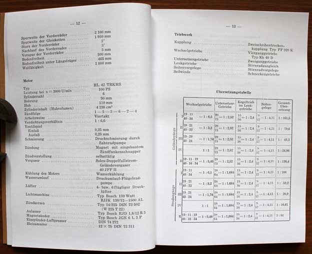
So............ If you work everything out using infobox π/4 = 0.78539816, and high precision for 1 cylinder, (eg 10 decimal places, I don't want to get dragged into signifcant places), and use only 3 decimal places (also non-significant) for the total capacity of 6 cylinders, you get to Maybach's value of 4 198 cc. Which is what I'm looking for. MinorProphet (talk) 10:57, 20 December 2023 (UTC)
Table 1 edit
| Engine | Power (PS) | @ rpm | bore/ stroke |
Capacity (litres) |
Cylinders | Year | Notes | |
|---|---|---|---|---|---|---|---|---|
| HL10[1] | 70 | 5000 | 100 * 70 | 1.099 | I-2 | 1944[f] | fuel injection, auxiliary supercharger for HL232 | |
| Auxiliary motor to run the supercharger on HL232. NB Not a 'pup' for starting main engine'.[12] | ||||||||
| HL11 | 60 | 6000 | 75 * 60 | 1.06 | I-4 | 1944[f] | fuel injection, auxiliary supercharger for HL232 | |
| HL25 | 65 | 2800 | 2.54 | I-4 | 1936 | |||
| Applications: Pre-production Sd.Kfz. 10 D4 | ||||||||
| HL25 R | 2.54 | I-4 | 1943 | Diesel, auxiliary supercharger for HL232 R | ||||
| SHL25 | 60 | 2.54 | I-4 | 1937 | ||||
| HL28[g] | 100 | 3500[h] | 90 * 110 | 2.79 | I-4 | 1937 | ||
| SHL28 | 65 | 2.79 | I-4 | 1936 | ||||
| HL30[i] | 100 | 3500[h] | 95 * 110 | 3.11 | I-4 | 1939 | Aluminium alloy block | |
| HL33 | 120 | 3500 | 100 * 106 | 3.328 | I-4 | 1942 | fuel injection[j] | |
| HL35 | 140[15] | I-6 | 1935 | |||||
| NL35 | 90 | 3000 | 90 * 90 | 3.435 | I-6 | 1935 | ||
| NL38 | 100 | 3000 | 90 * 100 | 3.817 | I-6 | 1935 | ||
| HL38 | 140[16] | 4500No!![k] | 90 * 100 | 3.817 | I-6 | 1936 | ||
| HL42 | 100[l] | 3000 | 90 * 110 | 4.198 | I-6 | 1938 | Notes | |
| NL42 | 100 | 3000 | 90 * 110 | 4.198 | I-6 | 1935 | ||
| HL45 | 150[m] | 3000 | 95 * 110 | 4.678 | I-6 | 1939 | Aluminium alloy block | |
| HL49 | 115 | I-6 | 1936 | |||||
| HL50 | 180 | 4000 | 100 * 106 | 4.995 | I-6 | 1942 | fuel injection | |
| HL52 | 120 | 2800 | 100 * 110 | 5.184 | I-6 | 1934 | ||
| HL54 | 115 | 2600 | 100 * 115 | 5.419 | I-6 | 1937 | ||
| HL57 | 130 | 2600 | 100 * 120 | 5.698 | I-6 | 1935[n] | ||
| HL61[o] | 130 | 2600 | I-6 | 1938 | ||||
| HL62 | 140 | 2600 | 100 * 130[p] | 6.126 | I-6 | 1935 | ||
| SHL62[q] | 125 | 2200[r] | 100 * 130[s] | 6.126 | I-6 | 1937 | ||
| HL64 | 140 | 2600 | I-6 | 1942 | ||||
| HL66 | 180 | 3200 | 105 * 130 | 6.754[t] | I-6 | 1941 - 1943 | Aluminium alloy block | |
| SHL66 | 125 | 2200[u] | 105 * 130 | 6.754 | I-6 | 1939 | ||
| HL67[v] | 176 No!! Yes, diesel version[18] |
3500 | 100 * 106 | 6.660 | V-8 NB!! |
1942 | fuel injection - diesel version also tested.[w] | |
| HL68 | 150 | 3000 | 6.75[x] | I-6 | 1938 | [y] | ||
| HL85 | 185 | 2600 | 95 * 100 | 8.505 | V 12 | 1938 | ||
| HL87 | 280 | 8.7 | I-6 | 1941 | Diesel | |||
| HL90[z][20] | 360[j] | 4000[aa][j] | 100 * 106[ab] | 9.990 | V 12 | 1941 | fuel injection - a possiblity - orig. table states 3,500 rpm. | |
| HL95 | 230 | 9.57 | V 12 | 1938 | ||||
| HL98[ac] | 230 | 2600 | 95 * 115 | 9.782[ad] | V 12 | 1938 | ||
| HL100[22] | 300 | 3000 | 100 * 106 | 9.990 | V 12 | 1934 ?[ae] | ||
| HL100 | 400 | 4000 | 100 * 106 | 9.990 | V 12 | 1943 | fuel injection, predecessor of HL 101 | |
| HL101 | 510 / 700[af] |
3800 | 11.9 | V 12 | 1944 | fuel injection, also a supercharged version; diesel version also tested, 300 PS???[25] | ||
| HL108 | 230 | 2600 | 100 * 115 | 10.838 | V 12 | 1938 | ||
| HL109 | 230[ag] | 10.83 | V 12 | 1943 | ||||
| HL116 | 300 | 3000 | 125 * 150 | 11.048 | I-6 | 1938 | Aluminium alloy block | |
| HL120 | 300 | 3000 | 105 * 115 | 11.949 | V 12 | 1936 | ||
| SHL120 | 300 | 3000 | 105 * 115 | 11.949 | V 12 | 1937 | ||
| HL140 | 250 | 13.84 | I-6 | 1939 | Diesel | |||
| HL150[26] | 400 | 3400 | 150 * 150 | 15.904[ah] | I-6 | 1939 | ||
| HL157 P[27] | 550 | 3500 | 15.58 | V 12 | 1942?[ai] | |||
| HL174 | 550 | 3000 | 125 * 130 | 19.144 | V 12 | 1940 | Aluminium alloy block?? Definitely not a diesel.[28][aj] | |
| HL190 P | 400 | 18.99 | V 12 | 1939 | ||||
| HL210 | 650 | 3000 | 125 * 145 | 21.353 | V12 | 1942 - 1943 | Aluminium alloy block | |
| HL211[30] | 125 * 145 | 21.353 | V12 | 1938+ | Diesel version of HL210 | |||
| HL224[ak] | 600 | 3000 | 125 * 145[al] | 21.353 | V 12 | 1940 | Aluminium alloy block | |
| HL230 | 700 | 3000 | 130 * 145 | 23.095[am] | V 12 | 1943 - 1945 | Cast iron block, last wartime production engine | |
| HL232[an] | 1,000 / 1,200[ao] |
130 * 145 | 23.095 | V 12 | 1944[ap] | fuel injection, supercharged with either HL10 or HL11 | ||
| HL232 R[aq] | 130 * 145 | 23.095 | V 12 | 1943 | Diesel, supercharged with diesel HL25 R | |||
| HL232 RT | 130 * 145 | 23.095 | V 12 | 1943 | Diesel with turbocharger | |||
| HL234 | 900 | 130 * 145 | 23.095 | V 12 | 1944[f] | fuel injection, without supercharging | ||
| HL235 | 130 * 145 | 23.095 | V 12 | 1949 | ||||
| HL280 | 700 | V 12 | never | Almost certainly a misprint for HL230 | ||||
| HL295[20] | 1000 | 2800 | 140 * 160 | 29.556 | V 12 | 1945 | fuel injection, without supercharging[ar] | |
| HL320[32][as] | 600 | 145 * 160 | 31.705[at] | V 12 | 1937 | |||
| HL337 RT | 1000 | 2400 | 145 * 170 | 33.686 | V 12 | 1947 | Diesel turbo | |
| HL338 RT | 1000 | 2400 | 33.686 | V 12 | 1947 | Diesel turbo | ||
Calculated number of rows in above table using {{table row counter|id=Table1|ignore=5}} = 60.
Later engines
German tank motor for promising French tanks Yuri Pasholok, 10 March 2024 with plans of AMX-50 with HL295
Machine trans: "Diesel engines HL 337 RT and HL 338 RT were also developed for the French during this period, both developed 1000 hp at 2400 rpm, but the matter did not go further than the prototypes."
In total, 10 HL 295s manufactured, and at the end of the work under the AMX 50 program, it was “strangled” up to 850 hp, clearly for a reason... Such an engine stands in the AMX 50B prototype, which is located in the Tank Museum of the city of Saumur. The only available Maybach HL 295 is located in the Military-Technical Museum, Koblenz, Germany.
Table 2 edit
Diesel engines:
- HL87
- HL140
- HL174 (No!?)
- HL 211 with same cylinder dimensions as the HL210,
- HL232 R, supercharged
- with auxiliary diesel power unit HL 25 R.
- HL232 RT with a turbocharger.
Diesel versions of the HL67 and HL101 were also tested, developing 176 and 300 PS respectively with 4-valve heads and different shaped piston crowns.
| Engine | Power (PS) | rpm | bore/ stroke |
Capacity | Cylinders | Year | Notes | |
|---|---|---|---|---|---|---|---|---|
| HL25 R | Diesel | |||||||
| Auxiliary diesel power unit for supercharged diesel HL232 R | ||||||||
Table 3 with colours edit
| Engine | Power (PS) | @ rpm | bore/ stroke |
Capacity (litres) |
Cylinders | Year | Notes | Fuel | Block |
|---|---|---|---|---|---|---|---|---|---|
| HL42 | 100[au] | 3000 | 90 * 110 | 4.198 | I-6 | 1938 | Notes | Gas | Cast |
| HL100 | 400 | 4000 | 100 * 106 | 9.990 | V 12 | 1943 | predecessor of HL 101 | F |
Notes
- ^ The author may have been attached to Tiger Battalion 502/503?
- ^ On motorcyle boxer engines such as the BMW (e.g. the R75), if the bike falls over on its side, exactly this problem can occur, and the engine won't turn over; the fix is to remove the lower spark plug, which drains the neat fuel out of the affected cylinder.
- ^ This may refer to the man-powered Schwungkraftanlasser inertia starter[8]
- ^ Full explanation: In a normal four-cylinder engine, the exhaust valve in one cylinder is open during the inlet stroke, while it is closed in the other cylinders which are on their compression, power and exhaust strokes. In an eight-cylinder engine, two cylinders are on the inlet stroke at any given moment, and three in a 12-cylinder motor, so there could be up to three cylinders affected. With the other nine cylinders functioning normally, the engine would tend to continue attempting to turn over and start until the bent conrods would tend to seize up the whole engine.
- ^ The death of a Walter Häring aged 98 on 9 January 2020 was reported in a Parish Newsletter in Weingarten, Württemberg, which is only 25 kilometres (16 mi) from Friedrichshafen.[10] He had some poetical ability: the previous year some of his verses were recited during a musical concert in Bad Buchau, some 60 kilometres (37 mi) from Friedrichshafen. "Für den 98jährigen Verseschmid Walter Häring aus Weingarten, rezitierte Rosi Schorr mehrere seiner Gedichte" [11]
- ^ a b c Official Maybach drawings of the HL234 still exist, see From the Archives: Maybach HL 234, Riased Bussians, January 14, 2018. Although faint, the date of the drawings seems be immediately above the Maybach 'double M' logo in the info box, in the column marked Tag, ie 'day'. Many appear to be dated March 1944: e.g. Valve Rocker Lever Roller appears to be 12.III.44, ie 12 March 1944. Also adjusted dates of HL10 and HL11 accordingly.
- ^ Used in the Adler HK.300 prototypes A2 and A3F in 1939, in competition with the Demag Sd.Kfz. 10. Never reached series production.[13]
- ^ a b Although it apparently dates from 1937, the max. revs are the same as later fuel-injected engines from around 1942. Hint: sort table by @rpm column
- ^ Used for two Adler protoype vehicles for a 3-ton tractor, 'Leichter Wermacht Schlepper', built in 1942 and 1943. Discontinued in 1944, a third example was intended to have a Maybach Olvar g/b, but no further details.[14]
- ^ a b c d More at: Talk:List of WWII Maybach engines#Finally, some proper answers.
Source for this following note:- Zima S. (1987). Entwicklung schnellaufender Hochleistungsmotoren in Friedrichshafen. (Reihe: Technikgeschichte in Einzeldarstellungen, Band 44/1987) ["Development of high-speed high-performance engines in Friedrichshafen". (Series: History of technology in individual representations Volume 44/1987) ] (in German). ISBN: 9783181500446.
"After the first series of engines was finished c1940, a new range of engines was proposed, all with [one-piece?] cast aluminium alloy engine blocks: I-4 HL30 (100 PS), I-6 HL45 (150 PS), HL66 (180 PS) & HL116 (300 PS), and a V-12 HL 224 (600 PS). Most of these had different cylinder dimensions except the HL30 and 45. Although a few engines were built and bench-tested, none reached production. There was also the HL90 from c1939, 100 x 106mm, 360 PS @4000 rpm. 14 of these were made, fitted to perhaps Panzer II Luchs, and /or perhaps VK 9.03 Panzerbeobachtungswagen [1] NB These cylinder dimensions actually result in a V-12 of 9.99 litres, which may be the source of the strange HL90/100.
In c1942, Maybach decided to consolidate its designs, using just two cylinder sizes: 100 * 106 mm (0.8325 litres), and 125 * 145 mm (1.92 litres). This resulted in five engines, four using the smaller cylinder: I-4 HL33 (120 PS), I-6 HL50 (200 PS), V-8 HL67 (240 PS), V-12 HL100 (400 PS); and the V-12 HL230 (700 PS). The HL50 and HL100 reached max. power @4000 rpm, which probably indicates fuel injection: most of the older engines developed max. power @ c.3000 rpm. There was a proposal to increase the HL100 cyl. dimensions to 105 * 115 mm [which works out as 11.95 litres], definitely with fuel injection, to develop 600 PS @3,800 rpm. But...
a) The article says that the 125 * 145 mm cylinder relates to the HL230. However, these are definitely the dimensions of the alloy block HL210, and I suspect a mistake somewhere.
b) The proposed expansion of the HL100 to 105 * 115 mm: this is what Spielberger says is the HL101, V-12, 105 * 115mm, 11.94 litres, 510 PS @3800.[1] Again, a huge discrepancy in power, but the cylinder dimensions tend to indicate it is the same engine. How Maybach came to name it the HL101 when it should have been an HL119 is something of a mystery.
The HL230 was developed into at least two more engines of greater power, none completed by the end of the war:
HL232, fuel injected and supercharged, developing 1,000 PS with its own auxiliary engine, the 2-cyl 1-litre HL10; or up to 1,200 PS with the 4-cyl 1.06 litre HL11 (60 PS @6,000 rpm.)
HL233, no details. See From the Archives: Maybach HL 232 and 233
HL234, fuel injected only, described on the main page. Power increased from 800 to 940 PS on the test bench by the end of 1944. All the 230 series engines had the same cylinder dimensions.
Maybach also designed and built a number of diesel engines starting in late 1938: HL87, HL140 and HL174; HL 211 with same cylinder dimensions as the HL210; and the supercharged HL232 R with auxiliary diesel power unit HL 25 R. There was also a diesel HL232 RT with a turbocharger. Diesel versions of the HL67 and HL101 were also tested, developing 176 and 300 PS Really??? Should be much more respectively with 4-valve heads and different shaped piston crowns. Like almost all these engines described above, none reached series production. [End of quote]
- NB The list of diesels above includes the HL174. There is considerable misinformation about this engine. J&D say there were only two ever made. If the pic reffed in the table above {{#HL174}} is correctly captioned, it was definitely not a diesel. Anyway, why would they stick a diesel in the last pre-production version of the Tiger I Ausf. E?
- Zima S. (1987). Entwicklung schnellaufender Hochleistungsmotoren in Friedrichshafen. (Reihe: Technikgeschichte in Einzeldarstellungen, Band 44/1987) ["Development of high-speed high-performance engines in Friedrichshafen". (Series: History of technology in individual representations Volume 44/1987) ] (in German). ISBN: 9783181500446.
- ^ 4,500 rpm in 1936, just don't think so. But what is the correct figure? It's weirdly wrong. The NL38 did 3000 rpm anyway, it's unlikely to be much different. Ha! Vastly too much power for 1936, mefinks
- ^ Milsom 1975 says 110
- ^ (Spielberger 1998, p. 209) says 147 PS...
- ^ The RKM ordered 500 HL57s in October 1935.[17]
- ^ Proposed for VK 6.01, Panzer I Ausf. F in July 1938.(Pz Tr 1-2, p. 1-148)
- ^ These dimensions give 6.126 litres, which is fairly close to the originally claimed 6.191. No sources I have been able to discover state the cylinder dimensions, and only a very few sources give this weird capacity: Panzermotoren from www.lexikon-der-wehrmacht.de is the most comprehensive.
- ^ SHL = Sonderausfuehrung Hoch Leistungs (motor) used in Pionierschnellboote. See Which vehicles used the Maybach SHL 66 petrol engine? - web forum question. Also stuff about HL66 P, Pla and Z:
- PLa
- Z
- [In fact, I'm aware of only the HL45 Z, proposed for HKp 602/603 (prototype replacement for Sd.Kfz. 251.]
- ^ This may well be an error, compare 2600 rpm for HL62.
- ^ This is the only combination of bore & stroke which gives around 6.2 litres, if the suggested capacity of the model number is correct.
- ^ This is definitely the capacity of 105 * 130 in the original table.
Capacity = (bore2 (mm) * stroke (mm) * π/4 [0.78539823] * no. of cylinders) ÷ 1,000,000
1052 = 11,025 11,025 * 130 = 1,433,250
- 0.78539823 * 6 / 1,000,000 = 6.754, definitely, checked 3 times.
- ^ This is almost certainly an error, compare 3200 rpm for HL66.
- ^ Proposed by M.A.N. for a rebuilt La.S.100 (Pz.II Ausf. A-C), for what became La.S.138 (Panzer II Ausf. D), along with Maybach 7-speed transmission.(Pz Tr 2-3-2). Production versions of the D used the the HL62 + VG 14 4 79.(Pz Tr 2-3-6)
- ^ Like the HL101, diesel version had 4-valve heads and different shaped piston crowns.[19] Is this the same as a 6.5 litre V-8 proposed for Panzer II D & E in 1937? (J&D Pz Tr 2-3 p. 2-3-2)
- ^ Probably wrong
- ^ Original table stated "Faun".
- ^ Proposed as intermediate engine for Heuschrecke 10 etc. Only 14 ever made. Details seem scarce.
- ^ This could be an early fuel-injected engine, in which case 4,000 rpm is fine. Original table on which this is based stated 3,500 rpm but no refs.
- ^ See note below referring to Zima/NF (1987) review, where this is specifically mentioned. NB These cylinder dimensions actually result in a V-12 of 9.99 litres, which may be the source of the strange HL90/100.[j] Compare 'HL90/100', listed in Wespe – Heuschrecke (Waffen-Arsenal No. 66) by Joachim Englemann (1980) [NB note early date], p. 47, although the official technical data sheet on p. 34 states an HL66 for the vehicle. Spielberger (1993c), Panzer IV and its variants p. 160 and Spielberger (1998), Der Panzerkampfwagen Tiger und seine Abarten, p. 209 restates this engine name and specs.
- ^ A 200 hp Maybach HL76 was proposed for the MKA (mittlerer Kampfwagen fur Ausland), a proposed export version of Krupp's early design for what became the Panzer III. The HL76 was not complete/ready/tested by October 1937 and the DSO8 was proposed instead; and only one trial example of the MKA (using an HL98) was ever made.[21]
- ^ From dimensions, π = 355÷113
- ^ Proposed for D-B Zugführerwagen in 1934, tested in ZW1 and Zw4 (pre-production Panzer III) in 1935. {J&D Panzer Tracts 3-1, pp. 3-26, 28). Original table stated "DB, Krupp, MAN, Rheinmetall", which comes from the prededing para on p. 26...
- ^ Smaller version of the HL234; developed 500 PS without supercharger and 700 PS at 3,800 rpm supercharged, weight 600 kg.[23] Diesel version, like the HL67, had 4-valve heads and different shaped piston crowns.[24]
- ^ Most unlikely, seeing this engine was made in 1943 and was probably fuel injected. Compare HL108 above from 1938, developing the same power.
- ^ Original table had 16.95, but that's 150 * 160, what Spielberger states in PzKw Tiger und Abarten, p. 209, along with power of 320 PS.
- ^ Proposed for VK 16.02 Leopard, in development from mid-1941 through to January 1943. See J&D, Panzer Tracts 20-2.
- ^ Maybach only made two of these engines.[29]
- ^ Proposed for a 65-ton VK.6501(H) Heavy Tank in 1939/1940. 1 mild steel propotype made. Cancelled October 1940.[31] Probably only a very few engines made.
- ^ Same dimensions and capacity as HL210/211. Really? NB Spielberger, PzKw Tiger und Abarten, p. 209 gives these stats.
- ^ All the 230 series engines used the same cylinder dimensions.
- ^ Apparently proposed for an unbuilt E-100 project, From the Archives: Maybach HL 232 and 233. Date is murky, perhaps 25.2.44? Plans also exist at the IWM, see E-100 turret, Secret Projects. "Project B: Engine Maybach New Project 1200 hp 3000 turns/minute" The engine isn't named, but that's the only one which made that much power. Can't find a mention of it in a book.
- ^ 1,000 PS with the with its own auxiliary engine, the 2-cyl 1-litre HL10; or up to 1,200 PS with the 4-cyl 1.06 litre HL11 (60 PS @6,000 rpm.)
- ^ Plans exist: From the Archives: Maybach HL 232 and 233
- ^ R=Rohröl, lit. 'raw oil', diesel fuel
- ^ Used in French AMX 50 post-war prototype
- ^ "A 600/700 PS motor had been discussed by Dr. Maybach and WaPrüf 6 in October 1935 to power a proposed 30-ton tank. Dr. Maybach said that the current engine design parameters would need a 16-cylinder engine, 0.5 metres longer than a V-12, to develop 700 PS. The extra weight of a 700 PS engine compared to the increase in power, and weight of extra armour plate would be self-defeating. A 600 PS motor was provisionally decided on, although there was no contract for such a tank."[33] Maybach had yet to bench test an engine of even 300 PS. This last statement of mine is obviously wrong, the HL120 was making 300 PS in 1936
- ^ From given dimensions, π = 355÷113
- ^ Milsom 1975 says 110
References
- ^ a b c Spielberger 1998, p. 209.
- ^ Treue & Zima 2021, p. 360.
- ^ Treue & Zima 2021, p. 188.
- ^ Treue & Zima 2021, p. 216.
- ^ Pic at Leitmeritz (Litoměřice) Subcamp
- ^ Auto Union AG, Chemnitz and Zwickau, USSBS Report 84 p. 3.
- ^ Find ref!!!
- ^ You tube vid
- ^ Treue & Zima 2021, pp. 196–7.
- ^ "Freude und Leid" (PDF). Gemeindebrief - Evangelische Kirchengemeinde Weingarten: 36. May–July 2020. Retrieved 26 December 2023.
- ^ "Mitteilungen aus Bad Buchau" (PDF). Federsee Journal (21): 5. 16 October 2019. Retrieved 26 December 2023.
- ^ Diesel Engine Starting Systems p. 217 (pdf 2]
- ^ Spielberger 1998, p. 32.
- ^ Spielberger 1998, pp. 32–3.
- ^ REALLY???
- ^ REALLY REALLY???
- ^ Treue & Zima 2021, p. 168.
- ^ Zima/NF (1987)
- ^ Zima/NF (1987)
- ^ a b Pic at Разброд и шатание в немецком бронетанковом моторостроении [Squeezing and staggering in German tank engine construction] Yuri Pasholok. In Russian, 20.05.2022
- ^ (J&D, Panzer Tracts 03-01 Panzerkampfwagen III. Ausf. A, B, C & D, pp. 3-32, 3-39, 3-70)
- ^ Pic at How the Wehrmacht's Diesel Stalled. Dmitriy Zaitsev. 26 October 2020
- ^ Estes 2018, Appendix III p. 4.
- ^ Zima/NF (1987)
- ^ Zima/NF (1987)
- ^ (Jentz & Doyle 2000b, p. 10) Germany's Tiger Tanks, D.W. to Tiger I, for all these figures except exact capacity.
- ^ Spielberger, Walter (1993b). Panther & its variants. p. 219
- ^ Pic (with magneto) at VK 36.01: Half a Step from the Tiger. Yuri Pasholok. 23 June 2018
- ^ J&D 2000, p. 20
- ^ Zima/NF (1987)
- ^ VK.6501(H) Heavy Tank
- ^ Jentz & Doyle (2000b) Germany's Tiger Tanks: D.W. to Tiger I, p. 10. Gives all the stats except the revs.
- ^ Jentz & Doyle 2000, p. 9.
- Estes, Kenneth W. (2018). German Heavy Fighting Vehicles of the Second World War. From Tiger to E-100. Fonthill. ISBN 978-1-78155-646-7.
- Spielberger, Walter J. (2008). Halftracked Vehicles of the German Army 1909-1945. (Originally published as die Halbketten-Fahrzeuge des Deutschen Heeres 1909-1945). Illustrated by Hilary L. Doyle and Uwe Feist. Translated by Edward Force. Atglen, Pa: Schiffer Military History. ISBN 978-0-7643-2942-5.
More Panther tech data - move to ZF gearboxen draft edit
Lots of tech data on the Panther
Spielberger, Panther tank and variants, p. 221, says the Olvar was physically shorter than the AK 7-200.
In Appendix 2, p. 235 (NB not by Spielberger), Maybach & licensees made a total of 7000 Panther engines and 2000 Tiger ones (HL230 P45). The AK 7-200 weighed 750 kg., engine dimensions length 1310 mm x width 1000 mm x height 1190 mm. (p. 236)
Better: HL230 P45 power = 700 PS @3,000, torque = 185 mkg @2,100 rpm. (p. 235) Excellent. The clutch, a Fichtel & Sachs LAG 3/70 H could transmit 200 mkg at max rpm (ie 3,000). Even better.
The gearboxes were assembled at Waldwerke Passau; Steyr-Daimler-Puch in Graz-Thorndorf (Austria??) and Lanz in Mannheim also made components (and/or assembled them. (p. 236)
The magnetos (with impulse starter installed) were JGN 6/R 18 (p. 237) The 24 V electric starter used 2 x 12 V batteries in series.
Even more re Panthers: Appendix 8, Panther Btn. combat report (When?), said that some 30 tanks in constant combat for 6 days travelled an average of 700 km, with only 11 engine changes. Only 6 tanks were completely put out of commission by enemy fire. Destroyed 89 tanks/assault guns, and 150 guns, AT and AA guns.(pp. 244-5)
Last meeting of Panzer Commission, 31 Jan 1945:
Panzerjager 38D (German version): Torque could be improved from 48 mkg (with what engine?) to 78 mkg with the Tatra diesel engine, although it was almost impossible to fit into the design. "The gearbox" had double the torque of "the Wilson gearbox" with only 15% weight increase. (Spielb/ Panther, p. 258)
- NB A Wilson mechanism definitely relates to the clutch-steering gear and final drive, not the change-speed box. Obviously(?) all the components in the drivetrain need the same torque capacity.
The MM (Maybach Motoren) HL230 in the King Tiger only produced 540 PS at the governed 2,600 rpm. General Thomale (stub, needs expanding - see de:Wolfgang Thomale) expressly said that the new HL234 injection engine should NOT be rolled out until it has reached 100% maturity. (Ahem). (p. 258) Holzhaeuer wanted the 8-cylinder Tatra diesel for the 38(t), the 8-ton half-track (Sd.Kfz. 7) and the SWS, which would include the ZF AK 5-80 gearbox. Maybach proposed an HL64 with fuel injection instead of the Tatra, giving roughly 270 PS rather the 210 of the Tatra. (p. 259)
Finally: use of the AK 5-80 in the Panzer II (still???) and IV, and the AK 7-200 in the Tiger II needed to be planed for. Two Tiger IIs with AK 7-200s had been tested in Kummersdorf and there was no question about their reliability. [Even so, they still used the Olvar in the production vehicles.] (p. 260), 31 January 1945.
Flakpanzer based on Panther chassis: (Spielberger, Panther tank and variants p. 214)
- "Krupp proposed the use of the following tank components:
- — Track and running gear of the Panther (Leopard armored reconnaissance vehicle running gear was not adequate, since the larger road wheels brought about an increase in the muzzle height by approximately 100 mm)
- — Maybach HL 157 engine with 550 hp (Aufklärungspanzer Leopard) - seems to be a correct figure...
- — ZF AK 7-130 gearbox (Aufklärungspanzer Leopard) - another one for the ZF experimental table.

- — Steering mechanism from either the Leopard armored reconnaissance vehicle or, considering the great length, possibly an in-house design." (Spielberger, Panther tank and variants p. 214)
- And on p. 220, the test vehicles used an HL90, 360 hp @ 3,600 + ZF SMG 90, and proposed series would have used HL157, 550 hp @3,500 rpm. This is confirmed by Pz. Tracts 20-2, Paper Panzers Vol 2 p. 20-66 and 20-94) - 'Leopard': 550 PS @3,500 or 3,600 rpm - perhaps fuel-injected.
References
Panzer II info (not important at all) edit
- According to the contents page of Spielberger, Walter J. (1974). Die Panzerkampfwagen I und II und ihre Abarten (in German). Illustrated by Hilary L. Doyle and Uwe Feist. Motorbuch Verlag Stuttgart. ISBN 3879433356., the Panzer II was produced with variants in the following order: Prototypes: Ausf. a1-3, b1-3; main production series A, B, C, F. D, E; G1, G2, G4, J, H, M, n.A. (neue Art, new type), L (Luchs); Leopard (a 'paper panzer'). In a separate category: Pz II (F) Flamm on A & B. How do Jentz and Doyle put it?
Ernst Kniepkamp edit
(sometimes Ernest)
[Short biographical sketch of Kniepkamp in Spielberger, Panther tank and variants p. 230]
Well, he was fairly obviously an experienced design engineer, many patents including torsion bars and possibly gearboxen as well. Are any on Google patents? or any other database?
BIOS Report #36/18 (in Estes) said he joined the German Army Ordnance in 1926, was concerned with tank development from then.
He must have been good at staying in his job, coz he was in WaPruf 6 until almost the end of the war.
Lots of info here: https://www.livesteammodels.co.uk/dhmg/kettenkrad01a.html
- "He was born in 1895, in Wuppertal, Germany. Presumably he would have served in the military during WW1, however I have seen no mention of it. After World War I he graduated in the Technische Hochschule de Karlsruhe. From 1923 he worked in the design of transmissions in the MAN company until 1925/26."
- "He worked for the MAN company for 3 years prior to employment at Heereswaffenamt (loosely Military Weapons Office)." "Finished the war as a General - photo shows Colonel uniform? Iron Cross WW1?"
- "The date that Herr Kniekamp becoming head of Wa Pruef 6 seems to be a source of confusion. Most sources state that he was appointed as its head in 1936. However, another source states that an Oberst Sebastian Fitchner (Colonel in the English world) was head from 1936 until 1942 and that during that time, Kniepkamp was responsible for all new tank development projects - effectively Panzer III and IV and then Tiger I, Panther and Tiger II. There is a story that Kniepkamp was over ruled about the suspension design for the Pz III and IV and if he wasn't the head of Wa Pruef 6 during that period then the story does make sense.
- "Noteworthy is the fact that Fitchner and Kniepkamp together were reported to have visited Guderian's 2nd Panzer Army on 18th November 1941 to study the Russian T-34 which was causing so much trouble - from this visit came the requirement that eventually resulted in the Panther tank. "
- "Working for Wa Pruef 6 he effectively designed the overlapping wheels, torsion bar suspension and redundant steering if front wheel(s) removed concept and lastly the lubricated track system BUT not the whole of any vehicle."
Stuf edit
- Drawer B2, Folder 300080-01. Germany, Engines, Ernest Kniepkamp. Notes: Documents. [1]
List of actual designs edit
- Sd.Kfz. 6,D ll 1, Demag Lilliput 1 (LL for clarity). 1934-1935 (PzTr 22-1-2 & -3) NB! Versuchs-Serie (VS projects) were paid for by Wa Pruf 6, usually limited from two to five vehicles. (PzTr 22-1-5) The D4 pre?-production series used an HL25 (65 PS @ 2,800 - 22-1-5) or 3,000 (Milsom 1975 p. 86)
- Kettenkraftrad Sd.Kfz. 2, HK 101 - his initals?
Refs edit
References
- ^ National Air & Space Museum Technical Reference Files: Propulsion NASM.XXXX.1183.B (Series B2: Propulsion: Engines, General). url=https://sirismm.si.edu/EADpdfs/NASM.XXXX.1183.B.pdf National Air & Space Museum Technical Reference Files: Propulsion. last=NASM Staff. 2017. (Held at Udvar-Hazy center. More specific information can be requested by contacting the Archives Research Request. https://airandspace.si.edu/archives-research-request - They seem happy to help with specific requests, but replies take 3 weeks by snail mail...!