For Frequency counter edit
Operating principle edit
Most frequency counters work by using a digital counter which counts the number of events occurring within a specific precise period of time, the gate time or gate period. During the gate period, the counter is incremented by each oscillation of the input signal. At the end of the gate period, the number in the counter is transferred to a digital display and the counter is reset to zero in preparation for the next counting cycle. The gate timing signal is generated by an internal electronic oscillator called the timebase, divided down by decade counters. For example, if the gate time is one second, the count represents the average frequency of the input signal in hertz.
The timebase must be calibrated very accurately, for it determines the accuracy of the frequency measurement. Precision crystal oscillators are used. Oven controlled crystal oscillators (OXCOs) can achieve accuracy of around 10-11.
If the signal to be counted is already in electronic form, simple interfacing to the instrument is all that is required. Cyclic processes that are not inherently electronic, such as sound waves, mechanical vibrations or the rotation rate of a shaft, can be converted to a repetitive electronic signal by a transducer and the frequency measured by the counter. In the instrument, the input signal is put through a comparator before applying it to the counter, which converts it to a square wave with fast transitions to improve the accuracy of the counting process. More complex signals may need additional conditioning to make them suitable for counting. Most general purpose frequency counters will include some form of amplifier, noise filtering and shaping circuitry at the input. DSP technology, sensitivity control and hysteresis are other input processing techniques used to improve performance.
When the frequency of the input signal is low compared to the gating interval, so only a small number cycles are counted, the resolution of the measurement will be low, and the quantization error (described below) will be significant. In this case it is usually more accurate to measure the period of the signal rather than the frequency. Frequency counters accomplish this by exchanging the roles of the input signal and the gating signal in the counting process, so the number of cycles of the gating signal in a single cycle of the input are counted. A higher frequency gating signal is used in this case.
Frequency counters can measure frequencies up through the radio frequency range and even into the microwave range. In microwave frequency counters the input signal is often put through a prescaler, a digital divider which reduces the frequency to . The maximum frequency that can be measured is limited by the maximum speed that digital counters can work. Frequency counters currently can cover the range up to about 150 - 200 MHz. Frequencies above this must be measured by indirect techniques.
Analysis edit
It can be seen from the description above that the frequency count will be:

If Ti is the period for one cycle of the input signal, and Tg is the gate time, fi = 1/Ti is the input frequency, and fg = 1/Tg is the frequency of the gate signal. So the frequency of the input signal is given by:

Quantization error edit
The uncertainty of ± ½, or one count, shown above is called quantization error or gating error and is due to the fact that the input signal is asynchronous to the gating signal. Depending on where the gate window falls in the input stream during each counting interval, it may randomly include one more transition of the input waveform, or not. The fractional quantization error is:

It can be seen that the quantization error is o
Most frequency counters work by using a counter which accumulates the number of events occurring within a specific period of time. After a preset period (1 second, for example), the value in the counter is transferred to a display and the counter is reset to zero. If the event being measured repeats itself with sufficient stability and the frequency is considerably lower than that of the clock oscillator being used, the resolution of the measurement can be greatly improved by measuring the time required for an entire number of cycles, rather than counting the number of entire cycles observed for a pre-set duration (often referred to as the reciprocal technique). The internal oscillator which provides the time signals is called the timebase, and must be calibrated very accurately.
If the thing to be counted is already in electronic form, simple interfacing to the instrument is all that is required. More complex signals may need some conditioning to make them suitable for counting. Most general purpose frequency counters will include some form of amplifier, filtering and shaping circuitry at the input. DSP technology, sensitivity control and hysteresis are other techniques to improve performance. Other types of periodic events that are not inherently electronic in nature will need to be converted using some form of transducer. For example, a mechanical event could be arranged to interrupt a light beam, and the counter made to count the resulting pulses.
Frequency counters designed for radio frequencies (RF) are also common and operate on the same principles as lower frequency counters. Often, they have more range before they overflow. For very high (microwave) frequencies, many designs use a high-speed prescaler to bring the signal frequency down to a point where normal digital circuitry can operate. The displays on such instruments take this into account so they still read true. Microwave frequency counters can currently measure frequencies up to almost 100 GHz. Above these frequencies the signal to be measured is combined in a mixer with the signal from a local oscillator, producing a signal at the difference frequency, which is low enough to be measured directly.
For Simple harmonic motion edit
In physics and mathematics, simple harmonic motion (SHM) is the motion described by a point that is the projection on the x-axis of a point moving at a constant speed in a circle about the origin. The motion is periodic; the point oscillates back and forth about a central equilibrium position (the origin) with a smooth sinusoidal motion, that is, given by a mathematical sine or cosine function. The time taken by a single cycle of the motion, that is a single rotation of the generating point about the origin, is called the period, T.
Since the motion is defined by a point on a circle, the position of the point at any particular time in its cycle can be described by its phase angle, the angle a line through the point makes with the x-axis. As point rotates, the phase angle increases steadily from 0 to 2π (360°), then starts over again at 0.
An example of an object that moves with SHM is a piston in an automobile engine, or a weight bobbing up and down on a spring. Simple harmonic motion describes the motion of many oscillating and vibrating objects in physics, known as harmonic oscillators.
Definition edit
The position of a point in simple harmonic motion is given at any time by the equation:


The motion is described by the three constants , , and :


- is the amplitude, the maximum distance the point moves away from the origin during it's oscillation. A is also the radius of the circle Since the point moves a maximum distance of +A from the origin during its positive excursion and a distance of -A during its negative excursion, the total width of the point's motion is 2A. This is sometimes called the "peak-to-peak" amplitude.
- is the frequency, the number of complete oscillations the point completes in one second, in hertz. The larger is, the more rapidly the point moved back and forth. It is the reciprocal of the period ( ): .
- is the phase; the position the point is in its cycle at = 0, described by the angle that the radius from the origin to the rotating point makes with the x-axis, in radians.


The frequency can alternately be replaced by the radian frequency:

in radians per second, which is the angle in radians that the generating point turns in one second instead of the number of cycles.

simple harmonic oscillator, a motion that is neither driven nor damped. A body in simple harmonic motion experiences a single force which is given by Hooke's law; that is, the force is directly proportional to the displacement x and points in the opposite direction.
The motion is periodic: the body oscillates about an equilibrium position in a sinusoidal pattern. Each oscillation is identical, and thus the period, frequency, and amplitude of the motion are constant. If the equilibrium position is taken to be zero, the displacement x of the body at any time t is given by
where A is the amplitude, f is the frequency, and φ is the phase.
The frequency of the motion is determined by the intrinsic properties of the system (often the mass of the body and a force constant), while the amplitude and phase are determined by the initial conditions (displacement and velocity) of the system. The kinetic and potential energies of the system are also determined by these properties and conditions.

Simple harmonic motion can serve as a mathematical model of a variety of motions, such as the oscillation of a spring. Other phenomena can be approximated by simple harmonic motion, including the motion of a pendulum and molecular vibration.
Simple harmonic motion provides the basis of the characterization of more complicated motions through the techniques of Fourier analysis.
For Magnet edit
Simplified explanation edit
The magnetic field of permanent magnets is generated by the orbital electrons in their atoms. The electrons behave as if they spin about an axis like tops. This creates a tiny magnetic field.
In most materials, the electrons come in pairs. The electrons in these pairs are oriented with their magnetic fields in opposite directions, N to S, so their magnetic fields oppose one another and cancel. Permanent magnetism occurs only in substances that have atoms with unpaired electrons. In a few of these substances, iron and the other ferromagnetic materials, the unpaired electrons spontaneously align so their axes of spin are parallel, and their tiny magnetic fields reinforce each other and add together to make a strong magnetic field.
Considering the above, why isn't every piece of iron a magnet? Iron and other ferromagnetic materials are divided into millions of microscopic regions called magnetic domains that act like tiny bar magnets. Their size is of the order of 10-5 m.[1] In a piece of unmagnetized iron the magnetic domains point in different random directions, so their tiny magnetic fields cancel each other out and the iron has no net magnetic field. In a magnet, most of the domains are aligned with their North poles pointing in the same direction. So their tiny magnetic fields add to each other, creating a large magnetic field that extends out from the magnet into the space around it.
When another piece of iron or other ferromagnetic material comes near a magnet, the magnetic field of the magnet aligns the magnetic domains in the iron. The iron object becomes a magnet itself for as long as it is in the field of the other magnet. Unlike poles of the magnet and the iron are closest to each other, North to South, so they attract. <improve>
In 'soft' magnetic materials like ordinary iron, the magnetic domains can easily turn their direction of magnetization, so once the external magnetic field is removed the domains tend to attract one another and lose alignment, pointing in random directions again, so the material doesn't stay magnetized. In contrast, in 'hard' magnetic materials used to make permanent magnets, the domains are 'pinned down' by the crystal structure and can't turn their direction of magnetization easily. Once the domains are aligned they tend to stay aligned, and the material stays magnetized.
For Magnetic domain edit
Domains in an external magnetic field - hysteresis curve edit
For Talk:Crystal radio edit
I agree with your point that the "threshold" of a diode is an optical illusion, depending on the scale of the vertical (current) axis. Nevertheless the forward "voltage drop" of a detector diode is still an important factor in crystal set design. The lower the "voltage drop" across the diode at any given voltage, the higher the "detection efficiency", the ratio of DC current to applied AC voltage.
"naive" crystal radio circuit:
Full wave crystal circuits:
- [17] p.17
Direct coupled impedance matched circuits:
Untuned crystal radio circuit:
Inductively coupled set with buzzer attached to ground wire"
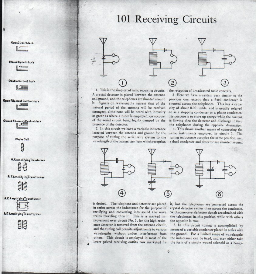
- [http://www.crystalradio.net/crystalplans/coolplans/101circuits/101-01.jpg 101 Receiving Circuits
For Mach's principle edit
.jpg)
Mach's principle is an imprecise conjecture in physics and cosmology, first advanced by Austrian physicist Ernst Mach in 1910 and named and popularized by Albert Einstein, that is variously said to consist of two related ideas: (1) that accelerated motions are relative; meaning that acceleration or rotation of an object can only be defined by comparing its motion relative to other objects, so there is no way to define "absolute" acceleration or rotation, and (2) that inertial forces on an object, such as centrifugal force, are caused by other matter in the universe.
This principle was a guiding force for Einstein in his development of the General Theory of Relativity in 1916. As indicated by the name he gave it, Einstein initially believed his General Theory of Relativity established that all motion is relative, and so proved Mach's principle, but later he gave up this view. The General Theory does predict, in conformity with idea (2) of Mach's principle above, that inertial forces on an object are caused by the distribution and motion of other matter in the universe. For centrifugal forces this is called the Lense-Thirring effect, and recent experiments, such as Stanford's Gravity Probe B, have begun to confirm its existence. However the statement of Mach's principle is somewhat imprecise, and there has been debate ever since about idea (1) above, that accelerated motion is relative, and whether modern relativistic physics and cosmology supports it or not.
Explanation edit
An example will show the relation between the two ideas introduced above. If an ice skater is spinning, it appears to her as if she is stationary and the surrounding skating rink, buildings, the Earth, Sun and the stars, and the entire universe, are spinning around her in the opposite direction. Mach's principle says that this is an equally valid way of looking at the situation, and there is no way of determining which is "actually" rotating. However, the skater feels a force pulling her arms away from her body. According to classical Newtonian physics this force, actually a pseudoforce called centrifugal force caused by the inertia of her body, indicates that she is actually the one rotating, not the universe. In fact, if she was unable to see other objects, with no other objects in the universe to refer her motion to, this centrifugal force would be the only way she could tell if she was rotating or not. Newtonian physics says that there is a distinction between rotating and nonrotating or inertial reference frames, that if she was not rotating but the universe was rotating around her, there wouldn't be a force pulling her arms outward.
Mach's view was that, if the universe was rotating, she would still feel her arms pulled outward. In the Machian view, centrifugal force is an effect caused by the relative motion of all the other mass in the universe; and a circulation of mass around an object would cause an outward force identical to centrifugal force. The only thing the centrifugal force on the skater indicates is a relative rotation between the skater and the other masses in the universe, so it can't distinguish which is "actually" rotating, or whether perhaps both are rotating at different rates. So in the Machian view, the concept of absolute rotation has no meaning.
Similarly, the Machian view is that linear acceleration is also relative. A person in an accelerating car is pressed into his seat by a force caused by his body's inertia. In Mach's view if the car was stationary and the universe was accelerating backward instead, this inertial force would still be present.
The idea that unaccelerated motions are relative is a cornerstone of both Newtonian and modern relativistic physics, accepted since the time of Galileo. It is expressed by the concept of an inertial reference frame. A person moving at a constant speed in a straight line can only determine whether he is moving, and in which direction, by reference to other objects. Because the laws of physics work the same in any inertial reference frame, there is no experiment that can determine whether he is "actually" moving or stationary. Therefore there is no way to define a preferred "stationary" reference frame; all inertial frames are equivalent. Mach's principle would extend this idea to all motion, including accelerated motion (noninertial reference frames).
For Diplomatic bag edit
Legal theory edit
A diplomatic mission is a group of official representatives of one country present in another country. Most countries keep permanent diplomatic missions, called embassies and consulates, in many other countries. International law has long recognised that to do their jobs effectively, diplomatic missions need to be able to communicate freely and confidentially with their home governments. During the 16th and 17th centuries, waylaying and bribing couriers in order to read governmental communications was a common method of espionage between nations. In order to prevent these abuses, the ______ in ___ provided a legally protected channel for missions to communicate; the diplomatic courier and diplomatic bag. During the 20th century, in order to allow secure transport of larger items needed by missions, such as cipher machines and radio transmitters, the definition of a diplomatic bag was expanded to cover arbitrary sized containers.
International law protects diplomatic bags from search or detention, not just by the country hosting the mission, but by any other countries the bag must travel through. A diplomatic bag must be accompanied by a diplomatic courier with one exception: in order to allow air freight shipment, a diplomatic bag may be transported unaccompanied on an aircraft, with the pilot assuming legal custody of it during the trip.
For Horn (acoustic) edit
In acoustics a horn is a flaring tube or duct, narrow at one end and wide at the other, which serves to guide sound between an acoustic transducer and the open air. Horns are used as part of sound sources, such as loudspeakers, megaphones, and pneumatic air horns, to radiate sound waves produced by a diaphragm or other source efficiently into the air. Conversely, they can also be used as receivers to collect sound for a transducer such as a microphone or the human ear, as in an ear trumpet. The function of the horn is to serve as a gradual transition structure that matches the acoustic impedance of the sound source to the impedance of open air. This allows the sound source to couple with the air more efficiently, radiating more of its power as sound waves, so the sound produced is louder. The horn may also serve to direct the sound waves in a beam in a particular direction.
Horns are also used in musical instruments in the brass and woodwind families. In these devices, in addition to its use as a sound radiator, the horn serves as a resonator to generate the note. The column of air in the horn is made to vibrate in standing waves by a reed or the player's lips when the instrument is blown, producing sound vibrations which are radiated out the open end. The pitch of the sound produced is determined by the effective length of the horn tube; the longer the tube the lower the note.


.jpg)


Description edit
Horns usually consist of a flaring tube, with the small end or throat attached to a sound source or transducer, and the wide end, the bell or mouth, open to the air. The walls of the horn must be rigid to guide the sound, so horns are often made of hard plastic or metal. The shape of the tube, its flare, is critical to the acoustical properties of the horn. The minimum acoustical reflections and maximum efficiency is achieved with an "exponential" flare, a smoothly widening taper like a flower. Both horn loudspeakers and musical horns often have some type of exponential flare. The size and shape of the horn's mouth and its flare angle determine the radiation pattern or angular coverage of the sound. The shape of horns can be tubular (with a circular cross section) or pyramidal (rectangular cross section). Acoustic megaphones often have a simple truncated cone shape. In folded horns (reflex horns), to make the horn more compact, the sound path through the horn is bent by reflections into a zigzag shape. Public address horn loudspeakers are often this type, with part of the sound path inside a central projection within the outer horn. Large cabinet loudspeakers sometimes contain folded horns; the inside of the speaker cabinet is divided by partitions into a series of sound ducts of increasing size that function as a large horn.
Musical instrument horns must also serve as resonators, so they are generally longer than horns which serve as acoustic radiators. They are typically only flared for about half their length, with the other half of the tube having almost constant diameter. The length of the tube determines the frequency of the note produced; in general the longer the horn the lower the pitch. To keep the size of the instrument manageable, in many instruments the horn tube is bent into a folded or coiled shape. In valved horns like trumpets and slide horns like trombones the length of the tube is altered during playing, to change the pitch of the note produced.
How it works edit
A vibrating object or diaphragm is an inefficient sound source unless it is large compared to the wavelength in air of the sounds it produces. The wavelength of sound waves in air ranges from about 2 centimeters (1 in.) to 17 meters (56 ft). So, particularly at low frequencies, small sound sources, such as small loudspeaker diaphragms, human vocal cords and lips, and reeds used in musical instruments, can't radiate much sound energy into the air unless they vibrate with very large amplitude (large displacement). The amount of sound energy a vibrating object radiates is dependent on the acoustic impedance the air presents to it; When the dimensions of the surface are small compared to the wavelength, the
Horns can be divided into two categories; those in which the horn just serves as a radiator and reproducer of sound, as in loudspeakers, megaphones, and gramophone horns; and those in which the horn also serves as a generator of sound, as in musical instrument horns. These two types of horn have very different characteristics. In the former, the goal is usually to design the horn with a flat frequency response over the frequency range of interest, so the horn introduces as little distortion into the sound as possible. In musical instruments, in contrast, the horn cannot have a flat response because the sound is produced by resonances, at which energy is stored in standing waves in the horn. The musical tones it can produce are determined by the horn's harmonic series.
Uses edit
Horns are used as sound sources in:
- Horn loudspeakers
- Brass and woodwind musical instruments
- Vehicle horns
- Automotive horns - often have a horn radiator to amplify the sound made by a vibrating diaphragm.
- Bicycle horn - the traditional rubber bulb bicycle horn
- Air horns - used on trucks and trains,
- Disposable handheld compressed-gas horns - powered by an aerosol can of compressed air, they are used as warning horns on small sailboats and other small watercraft.
- Foghorns -
- acoustic cleaning systems - these are installed on material-handling systems that store or transport granular or powdered bulk materials, such as grain elevators. They use intense sound waves generated by horns to shake loose grains of material that build up on surfaces.
- Ultrasonic drill - This is an impact device that uses ultrasonic vibrations applied to a small flat bit like an impact hammer to drill holes in materials. It uses a solid "horn" made of a tapering steel rod in the opposite direction to other horns, to focus the ultrasonic waves generated by a wide piezoelectric driver to a very large amplitude applied to the bit.
- Megaphones - Before horn loudspeakers and electric bullhorns, acoustic megaphones were used to amplify the human voice, and also as speakers in gramophones.
Horns are used in sound reception applications:
- Ear trumpets - Before electronic hearing aids, horns were used by the hearing-impaired
- Acoustic aircraft detection - Before radar was invented in World War 2, acoustic detectors were used for air defence, to detect approaching enemy aircraft by the sound of their engines. These used large horns connected by tubes to stethoscope earphones.
- Early telephones often used horns on their handsets to deliver more sound power to the microphone.
History edit

Blown horns have been used from prehistoric times as signalling devices, made from animal horns and, in Pacific islands, from conch shells.[2] They often had religious significance, as with the shofar, a ram's horn used from Biblical times to the present day in Jewish religious rituals. Metal trumpets are mentioned in the records of pharaoh Tutankhamen dating to 1350 BCE, and the Biblical book of Numbers a few hundred years later.[2] The ancient Greeks attached conical horns to their theatrical masks to amplify the actor's voices. Ear trumpets, the first hearing aids, were probably used from ancient times[3] but detailed drawings appeared in the Renaissance. The mathematical theory of horns originated with Euler and Lord Rayleigh The first phonographs, lacking electronic amplification, used acoustic horns to increase the loudness of the sound produced by their needles, vibrated by the grooves in the record. One of the first folded horns was used in the Orthophonic Victrola, an acoustic phonograph. Before radar was developed in World War 2, huge "acoustic detection" horns were built by militaries in the 1930s to listen for the sound of enemy planes approaching. Horns have always been used with loudspeakers; the first loudspeakers developed in the 1920s all used horns. Today horn loudspeakers are mainly used in high power audio systems such as public address systems and concert sound systems needed to provide sound for large venues like auditoriums and sports stadiums. They were previously also used in home audio systems, but in recent years, due to their irregular frequency response and difficult design problems, horns have been superseded by more efficient cone speakers.
Flare edit

The acoustical properties of a horn are mainly determined by the flare, the rate of increase of the cross sectional area of the horn duct S(x) with distance x along the axis of the horn from the throat.
- Conical flare - The horn is shaped like a truncated cone, with straight sides.
- Exponential flare - The area of the horn increases exponentially, by the same factor for each unit distance. The walls of the horn curve smoothly outward like a flower.
- Catenary flare - Similar to the exponential flare
- Bessel flare - This is close to the traditional flare found in many horn musical instruments.
Webster's equation edit
The propagation of sound waves through a horn or other duct is described by Webster's equation, proposed by Arthur Webster[4] in 1919, although it dates back to Bernoulli.

where
- is the sound pressure along the axis of horn
- is the flare function, the cross sectional area of the horn as a function of distance along the axis
- is the speed of sound in air
- is the distance along the axis of the horn duct
- is time


The equation is derived by an approximation that assumes plane wave propagation; that the wavefronts are parallel planes normal to the axis, with the pressure and velocity uniform across the wavefront. It also assumes the acoustic displacement of air in the tube is parallel to the axis, neglecting the transverse motion that must occur because of the varying area of the tube. Therefore the equation is only accurate for gradually flaring horns, and gives large errors when the flare becomes too abrupt.
Morse condition edit
The exact condition for applicability of Webster's equation is given by the Morse condition, derived by Phillip Morse

where
- is the throat area
- is the flare rate


![[7]](http://www.crystalradio.net/crystalplans/xximages/makeparts2.jpg)
![[8]](http://www.crystalradio.net/crystalplans/xximages/fountainpen.jpg)
![[9]](http://www.crystalradio.net/crystalplans/xximages/radioelectronics1.jpg)
![[10]](http://www.crystalradio.net/crystalplans/xximages/loop1.jpg)
![[11]](http://www.crystalradio.net/crystalplans/xximages/smallfry.jpg)
![[12]](http://www.crystalradio.net/crystalplans/xximages/vestpocket1.jpg)
![[13]](http://www.crystalradio.net/crystalplans/xximages/umbrella5.jpg)
![[14]](http://www.crystalradio.net/crystalplans/xximages/electronics.jpg)
![[15]](http://www.crystalradio.net/crystalplans/xximages/vestpocketradio1.jpg)
![[18]](http://www.crystalradio.net/crystalplans/coolplans/Crystal%20Receiver%20Built%20From%20Junk%20Box%20Parts/XTL37021.jpg)
![[19]](http://www.crystalradio.net/crystalplans/xximages/radiocraft47jul1.jpg)
![[20]](http://www.crystalradio.net/crystalplans/xximages/children1.jpg)
References edit
- ^ Feynman, Richard P. (1963). The Feynman Lectures on Physics, Vol.2. Massachusetts, USA: Addison-Wesley. pp. 37–6. ISBN 0201021161.
{{cite book}}: Unknown parameter|coauthors=ignored (|author=suggested) (help) - ^ a b Montagu, Jeremy (2007). Origins and Development of Musical Instruments. USA: Scarecrow Press. pp. 104–105. ISBN 978-0810856578.
- ^ "Ear Wax Museum". Hearing Center online. Retrieved June 9, 2012.
{{cite web}}: External link in|publisher= - ^ Webster, Arthur Gordon (July 1919). "Acoustical impedance and the theory of horns and the phonograph". Proceedings of the National Academy of Sciences. 5 (7). USA: Natl. Acad. Sci.: 275–282. doi:10.1073/pnas.5.7.275. PMC 1091593. PMID 16576392.