Sonic anemometers edit

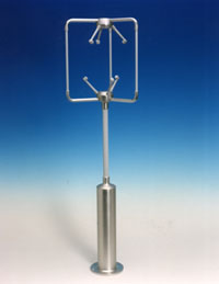
Sonic anemometers, first developed in the 1950s, use ultrasonic sound waves to measure wind velocity. They measure wind speed based on the time of flight of sonic pulses between pairs of transducers. Measurements from pairs of transducers can be combined to yield a measurement of velocity in 1-, 2-, or 3-dimensional flow. The spatial resolution is given by the path length between transducers, which is typically 10 to 20 cm. Sonic anemometers can take measurements with very fine temporal resolution, 20 Hz or better, which makes them well suited for turbulence measurements. The lack of moving parts makes them appropriate for long term use in exposed automated weather stations and weather buoys where the accuracy and reliability of traditional cup-and-vane anemometers is adversely affected by salty air or large amounts of dust. Their main disadvantage is the distortion of the flow itself by the structure supporting the transducers, which requires a correction based upon wind tunnel measurements to minimize the effect. An international standard for this process, ISO 16622 Meteorology—Sonic anemometers/thermometers—Acceptance test methods for mean wind measurements is in general circulation. Another disadvantage is lower accuracy due to precipitation, where rain drops may vary the speed of sound.
Since the speed of sound varies with temperature, and is virtually stable with pressure change, sonic anemometers are also used as thermometers.
Two-dimensional (wind speed and wind direction) sonic anemometers are used in applications such as weather stations, ship navigation, wind turbines, aviation and weather buoys. Three-dimensional sonic anemometers are widely used to measure gas emissions and ecosystem fluxes using the eddy covariance method when used with fast-response infrared gas analyzers or laser-based analyzers.
Acoustic Resonance edit

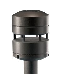
Acoustic resonance anemometers are a more recent variant of sonic anemometer. The technology was invented by Dr Savvas Kapartis and patented (Acu-Res®) by FT Technologies in 2000. [1] Whereas conventional sonic anemometers rely on time of flight measurement, acoustic resonance sensors use resonating acoustic (ultrasonic) waves within a small purpose built cavity in order to perform their measurement.

Built into the cavity is an array of ultrasonic transducers, which are used to create the separate standing-wave patterns at ultrasonic frequencies. As wind passes through the cavity, a change in the wave’s property occurs (phase shift). By measuring the amount of phase shift in the received signals by each transducer, and then by mathematically processing the data, the sensor is able to provide an accurate horizontal measurement of wind speed and direction.
Acoustic resonance technology enables measurement within a small cavity, the sensors therefore tend to be typically smaller in size than other ultrasonic sensors. The small size of acoustic resonance anemometers makes them physically strong and very easy to heat and therefore resistant to icing. This combination of features means that they achieve high levels of data availability and are well suited to wind turbine control and to other uses that require small robust sensors such as battlefield meteorology. One issue with this sensor type is measurement accuracy when compared to a calibrated mechanical sensor. For many end uses this weakness is compensated for by the sensors’ longevity and the fact that it does not require re-calibrating once installed.
Notes edit
- ^ European Patent No. EPO 801311 A and USA Patent No. 5,877,416 (1999)
External links edit
- Prinicple of Operation: Acoustic Resonance measurement - FT Technologies
Ultraschall-Windsensoren basierend auf akustischer Resonanz edit
Eine neuere Entwicklung auf dem Gebiet der Ultraschall-Windmessung basiert auf akustischer Resonanz[1][2]. Während konventionelle Ultraschallanemometer auf der Messung der Laufzeit basieren, wird bei den Windsensoren mit akustischer Resonanz eine Ultraschallwelle in einem kleinen Hohlraum reflektiert.
In dem Hohlraum befinden sich mehrere schwingende Membranen, die akustische Ultraschallwellen erzeugen und empfangen. Durch die wiederholte Reflexion zwischen den Reflektoren wird eine quasi-stehende Welle senkrecht zur Windrichtung und eine Transversalwelle parallel zur Windrichtung erzeugt. Strömt Luft entlang der Achse zwischen den Reflektoren, beeinflusst das die Ausbreitungsgeschwindigkeit der Welle und erzeugt eine Phasenverschiebung, die gemessen wird. Zum Ausgleich von Änderungen der Schallgeschwindigkeit, zum Beispiel durch Temperaturänderungen, wird die Ultraschallfrequenz kontinuierlich so angepasst, dass der Hohlraum in Resonanz betrieben wird. Dadurch wird die Messung der Luftgeschwindigkeit unabhängig von der variablen Schallgeschwindigkeit.
Aus aufeinander folgenden Messungen verschiedener Membranenpaare lassen sich die Vektorkomponenten der Luftströmung ermitteln und somit Windgeschwindigkeit und -richtung mathematisch berechnen.
Weitere Prinzipien edit
Nach der Bauart und dem Messprinzip unterscheidet man neben den oben schon erwähnten Anemometern:[3]
- Hitzdrahtanemometer (thermisches Anemometer): In diesem Fall wird ein Heizdraht erwärmt und mit Wind umströmt. So wird dem Draht Wärme entzogen und mit damit verbundenen Wärmeverlust kann auf die Windgeschwindigkeit geschlossen werden.
- Bei der Laser-Doppler-Anemometrie (LDA) wird mit Laserlicht aus zwei Richtungen ein stationäres Interferenzmuster aufgebaut. Von Strömungen in Fluiden mitgeführten Partikel streuen beim Durchgang durch das Interferenzmuster das Licht. Die Intensität des gestreuten Lichts wird gemessen und aus seinem Zeitverlauf die Geschwindigkeit der Strömung senkrecht zu den Streifen des Interferenzmusters ermittelt.
- Particle Image Velocimetry
- Surface Pattern Image Velocimetry
- Thermoelektrisches Anemometer
- Die Windstärke kann auch ohne die Verwendung eines Messgeräts anhand der Beaufortskala phänomenologisch abgeschätzt werden.
Einsatzbereiche edit
miniatur|Windmessung mit einem Hand-Anemometer Zusammen mit einem Windrichtungsgeber und einer Aufzeichnungseinrichtung sind fest installierte Anemometer Teil von Wetterstationen. Messdaten von temporären Anlagen in entsprechender Höhe sind für die Standortwahl und Auslegung von Windkraftanlagen notwendig. Auf größeren Flugplätzen werden meist von mehreren Messpunkten aus die Daten der Windmessung zur Flugüberwachung übertragen. Am oberen Ende vom Mast eines Segelboots ist häufig ein Schalenanemometer angebracht, das die Stärke des scheinbaren Winds ermittelt.
Siehe auch edit
Weblinks edit
Einzelnachweise edit
Kategorie:Windenergie Kategorie:Wind Kategorie:Meteorologisches Messgerät Kategorie:Flugmeteorologie