Talk:Transformer/Archive 5
| This is an archive of past discussions. Do not edit the contents of this page. If you wish to start a new discussion or revive an old one, please do so on the current talk page. |
| Archive 1 | ← | Archive 3 | Archive 4 | Archive 5 | Archive 6 | Archive 7 | → | Archive 10 |
possible split up of the article
- transformers
- physical principe
- scope of application
- transformers_(iron_core) (new article)
- power grid transformers (low power)
- signal transformers
- power transmission transformers
- transformers_(ferrite) (new article)
- power supply transformers
- flyback transformers
- filters (reference)
- transformers_(special) (new article)
- isolation transformer
- voltage transformer
- I wouldn't divide it up that way. I would take the construction portion and move it into a separate article; and I would take most of the items under "Transformer designs" and move them to separate articles. Pfalstad 14:19, 30 April 2006 (UTC)
- Does it really need splitting when its just got stable :-? --Light current 18:00, 30 April 2006 (UTC)
- Probably it will need splitting one day. These types of transformers are searched by different people. The pictures could be more/better quality. Probably the main page can take the principe of operation, and a gallery of two/three good pictures (buy a new transformer for that purpose). User:Akidd_dublin 9 may 2006
- I agree on dividing the article. It is too long.--Lenilucho 03:31, 10 May 2006 (UTC)
- General principles of transformers
- type A transformers (power freq, say)
- type B transformers (audio, say)
- etc ....--Light current 00:27, 17 May 2006 (UTC)
"Generally" is too vague
How about a citation for that paragraph that it is generally "safe" (whatever that means) to operate a transformer above its rated frequency? It's too vague and I don't know what specific instances it refers to if not for power transformers. Is it safe to operate a wall-wart on a 400 Hz aircraft supply? Too many qualifications required for this article's intention. --Wtshymanski 17:33, 16 May 2006 (UTC)
- I agree its vague. Its my experience! It actually refers to saturation of the core due to insufficient primary inductance. Saturation will not occur at higher frequencies if the applied voltage is the same. Do you not agree with this?
- Give me time to find some refS! What is the articles intention? 8-?--Light current 21:31, 16 May 2006 (UTC)
- Well Ive changed this now. But Im not really sure if it says anything new anymore. What do you think Bill?--Light current 02:12, 17 May 2006 (UTC)
Is there flux in the core, or is it cancelled out?
If no flux, then how does energy get from one side to the other?
If there's no flux in the core, how does energy get from the primary to the secondary? I have once again deleted the idiosyncratic assertion that an ideal transformer has no flux. --Wtshymanski 17:40, 17 May 2006 (UTC)
- No resultant flux!(apart from mag flux) Primary flux is cancelled by secondary flux, Its a feedback mechanism and its obvious to anyone. Pri flux cannot increase more than infinitesimally before it is cancelled by the sec flux. This again is obvious to any engineer! 8-)--Light current 23:48, 17 May 2006 (UTC)
- An ideal transformer, loaded with a pure resistance on its secondary, will look like a pure resistance at its primary terminals. ie no 'back emf' is detectable anywhere!! How can this be? 8-|--Light current 00:31, 18 May 2006 (UTC)
Good lord. Youth is wasted on the young. If I had your energy I'd be rich. If there's no flux, then *how* does energy get from primary to secondary? The article SAYS its the time rate of change of flux that produces the voltage in the winding (primary or secondary) - if there's no flux, its time rate of change is zero and there's no voltage! If the resultant flux in the core is zero, then we don't need the primary winding at all, and hey presto, we get energy from nowhere. I'd revert but you've got many valid edits in the last 1023 or so since I last saw the article yesterday. Saving every line as you change it helps get the edit count up, eh? --Wtshymanski 17:48, 18 May 2006 (UTC)
- I dont undertand your first statement. Unfortunately Im not rich. Does transfer of energy require flux? or just the threat of flux or mutual cancellation of flux?
- Let me try to explain it another way: Assume there is massive flux caused in the core by the action of the primary winding. However, there is equally massive flux in the opposite direction generated by the secondary current. These large rates of change of flux generate voltages. One is the applied primary voltage, the other is the secondary voltage.
- Do you agree that pimary AT = sec AT or not?(neglecting mag current).If so you can immediatly see there can be no resultant flux in the core. We need a primary winding to create an alternating magnetic field to cancel the flux generated by the secondary winding. Energy transfer is by the mechanism of mutual flux cancellation. Physically what does this mean? I dont know. What does flux mean?
- I will as you a converse question: Why do some transformers not need a core (trans line transformer et al?)
- Some times the thoughts come to me one by one. I save the page when I have entered a valid thought and then see that the page still makes sense overall. I do not have any interest in my edit count as such. I notice tho' that this seems to be an increasingly favorite form of attack from editors with low (usually very low) edit counts and some vandals.--Light current 18:18, 18 May 2006 (UTC)
- I have two references to the fact that the standard transformer analysis trests the transformer as having mutually opposing fluxes that sum to zero. They are listed in the article. You yourself (WTS) have stated that the MMFs cancel- so how can there be flux with no resultant MMF?--Light current 03:18, 25 May 2006 (UTC)
Others' comments
I don't have a lot to say about the question of flux/no-flux; I think the answer depends on how you define things and where you measure. I will suggest, however, that you forget the idea of "the core" versus "the air". The core is just a means to concentrate the magnetic flux and thereby increase the inductance, but short of core saturation and to a first approximation, there's no difference, in principle, between the way an iron core transformer and an air core transformer operates.
Atlant 18:25, 18 May 2006 (UTC)
- There is a magnetic flux in the core, and there's nothing subjective about it. There's a clear explanation on allaboutcircuits.com. I'll summarise it thus. The voltage across the primary creates a flux in the core. This flux depends only on the primary voltage, regardless of what the secondary is doing. Why? Because Ep=dΦ/dt, and Ep has constant amplitude; therefore, Φ, which is common to both windings, must have constant amplitude. If a load is connected to the secondary so that a current flows in it, then there is an invisible tug-of-war between the two windings. The secondary tries to induce an infinitesimal bit of extra flux, which is immediately and exactly counterbalanced by an infinitesimal increase in flux in the opposite direction from the primary, so the net flux stays constant. --Heron 19:32, 18 May 2006 (UTC)
- Well Atlant, I tend to agree with some of your above statement, but wherever you measure in the core, you will still find only the magnetising flux regardless of load current. I was trying to point out the need for flux cancellation in a loaded transformer. Highly permeable cores do, of course, concentrate the flux and increase pri inductance as well as increase coupling between windings.--Light current 22:58, 18 May 2006 (UTC)
- Yes Heron, I'm talking about when there is a secondary loading, in which case sec. current flows and the fluxes are cancelled. This is the normal operation of a transformer. Otherwise I agree with the last part of your post except that its the pri current (H =IN, B=uH, phi=BA) that creates flux in the core. Also, I submit the the net flux you quote is merely the magnetising flux - nothing more.--Light current 22:58, 18 May 2006 (UTC)
WTS to LC
Nom d'un chien. OK, nevermind a transformer. Take an ideal core out of your stock of physics thoguht-experiment supplies, wind some resistance-free wire around it, and impose a perfect sinusoidal voltage on the coil. The voltage across the the coil is proportional to the time rate of change of flux linked by the coil, right? It's a perfectly standard physics-experiment type inductor, correct? OK, now without telling your experimental apparatus anything, sneakily wind a second coil - my question is, how does the apparatus "know" that now it's an ideal transformer and so suddenly has no flux in it? --Wtshymanski 02:44, 19 May 2006 (UTC)
- Soon as sec current starts to flow, the core flux is completely cancelled by the sec MMF. Thats how the apparatus 'knows' that it has been transformed (into a transformer!) Simple! 8-))--Light current 13:02, 19 May 2006 (UTC)
- So a voltage being induced in an unloaded secondary is not a transformer? — Omegatron 04:14, 28 November 2006 (UTC)
- Correct! an induced voltage is not a transformer 8-)--Light current 04:17, 28 November 2006 (UTC)
- The rate of change of flux in the core is equal to the ratio of the voltage across the primary and the number of turns on the primary which is also to the ratio of the voltage across and the secondary and the number of turns on the secondary Thus, if we let the number of turns in the primary and secondary go to infinity (while, of course, keeping the turns ratio the same), the rate of change of the core flux goes to zero for any primary or secondary voltage. Assuming that at some time the core flux equaled zero, the core flux will thus remain zero. Further, this will yield a transformer that works at DC. While this condition is not usually stated as a property of an ideal transformer, it seems logical to me that a truly ideal transformer should work at an arbitrarily low frequency, right? Alfred Centauri 04:15, 19 May 2006 (UTC)
- Yes Alfred, I agree with you. Another way of putting it, though, is to say that instead of letting the number of turns approach infinity, we could let the permeability of the core approach infinity. This would form what I understand to be an ideal transformer (assuming zero R leads, no leakage ind etc) and indeed there is no reason why it should not work at an arbitrarily low frequency. AS you say 'the (net) core flux will remain zero' but we still have energy transfer! BTW the term DC is a difficult concept (cf arbitrarily low freq) -maybe to be discussed elesewhere 8-))--Light current 12:58, 19 May 2006 (UTC)
- Yes, Light current, it is true that that "net flux" I mentioned was the magnetizing flux. However, I am unhappy with your statement that "in an ideal transfomer they cancel so that there is no overall resultant flux in the core". Shouldn't you say "they cancel, leaving only the magnetizing flux"? We all seem to agree that the magnetizing flux exists regardless of whether there is a secondary winding or not, and regardless of whether any current is flowing in the secondary. As for the original question of "how does the energy get from one side to the other?", the answer seems to be that the magnetic field consists of two variables: MMF (F, in amperes) and flux (Φ, in webers) (see this paper from TI; PDF). Just as electrical power is the product of both voltage and current, magnetic energy is the product of both MMF and flux. (Check it dimensionally: MMF x flux = A x Wb = A x V.s = energy.) So, if you have no magnetizing flux, then you can't have energy transfer, but the flux by itself is not the energy. --Heron 09:46, 19 May 2006 (UTC)
- Electrical power is not an analog to magnetic energy. Power is the rate at which energy is transferred. — Omegatron 04:14, 28 November 2006 (UTC)
- Heron, depends how you are defining ideal. In an ideal transformer, I thought the magnetising inductance was infinite (inf perm core matl). In this case, there would no mag current and no mag flux required.
- So we should strictly say 'in a practical transformer the pri and sec fluxes cancel leaving only mag flux'. The energy must be the product of the MMF and the 'potential' flux. Trouble is, we dont know the potential flux until we have sec current flowing 8-). So again, it seems as if actual flux is not the primary agent of energy transfer. Maybe its the 'potential flux'. Energy transferred is not IMO the product of the MMF and the mag flux. If it were, then the ideal trans could pass no energy.
- Think about o/c voltage sources. What energy do they provide?--Light current 12:49, 19 May 2006 (UTC)
- I didn't realise that 'ideal' implied 'no magnetising flux', so I think I agree with you now. Perhaps the article needs to be explicit about what 'ideal' means. --Heron 18:26, 19 May 2006 (UTC)
Purpose of a transformer core
What is the real purpose of a transformer core since it seems there is no flux in it. 9-)--Light current 13:58, 19 May 2006 (UTC)
- To increase the efficency of the mutual coupling between the two (or more) coils. And as I think you guys finally argued, in transformer with a loaded secondary coil, there is instantaneous flux in the core proportional to the time-derivative of the voltage.
- Atlant 14:10, 19 May 2006 (UTC)
- If E=4.44fnab, and b is zero, and f,n, and a are finite -- then E must be zero. Got to have (changing) flux to make volts. --Wtshymanski 02:16, 25 May 2006 (UTC)
So if you could get perfect coupling, as with some transmission line transformers, you wouldnt need a core (indeed some transmission line transformers dont have one). No flux, no core-- this is getting weird. So what really is the essence of a transformer?--Light current 14:19, 19 May 2006 (UTC)
To enable complete cancellation of the magnetic field generated by the primary and thereby extract energy from the primary circuit, a core must be used to concentrate the field produced by the primary. and sec current must exist so that it can cancel this field. When the magnetic fileds are completely cancelled, all the input power is passed to the output. The core therefore acts merely as a conduit/coupling device to enable magnetic field cancellation.--Light current 14:56, 19 May 2006 (UTC)
- However, the magnetic fields never completely cancel, even in a perfect transformer. The primary winding has self-inductance. When the primary is driven by a sinusoidal voltage source, there is always an associated "magnetizing" current and magnetizing flux, irrespective of core material. For a non-lossy core and perfect wire, the magnetizing current will lag the applied voltage by 90 degrees so no real power is expended (i.e., a perfect inductor). Although it is true that incremental changes in primary and secondary fluxes cancel as the secondary begins passing current, this cancellation has NO impact on the magnitude of the underlying magnetizing flux. Note also that, for most ferromagnetic core transformers, the magnetizing flux is NOT small. In most designs, the magnetizing flux comes close to saturating the core. Bert 18:11, 19 May 2006 (UTC)
Bert, I agree there is always a mag current in a real transformer. Since this current is lagging the pri voltage (current) by pi/2, it is wattless (apart from heating up the windings a bit). THe cancellation I have been talking about does NOT include the mag flux. I thought I was pretty clear on that.
It is true that the value of mag current does not depend upon load current or power transfer but only on primary applied voltage. The magnetising current/flux is purely a consequence of the non infinite inductance of the pri winding and takes no part in the actual energy transfer between pri and sec. It seems to me that some editors think that the mag flux plays some essential part in this operation of a transformer and maybe they think it varies with load current. I can see you are not one of them. 8-) So we can say that there is no component of flux in the core that is in phase with the applied voltage/current in a real trans with resistanceless windings and k=1. 8-)--Light current 18:50, 19 May 2006 (UTC)
BTW the reason that mag flux comes close to saturating the core in most trans is that the designer is trying to save on wire for the pri wdg -- ie its an economical (or is it poor) design!--Light current 18:55, 19 May 2006 (UTC)
Blame it all on...
As part of our ongoing discussion, Light current asks:
- What IS a transformer? Curioser and curioser. 9-))
Blame it all on the magnetic monopole. Seriously, while we understand all of this EM stuff at a sufficient level to design and use technology based on electromagnetism, when you really get down to thinking about it, magnetism itself is still magic, a complete mystery to physicists. So if we start asking the really deep questions, the state of the art simply isn't advanced enough to provide answers. ;-)
Atlant 15:48, 19 May 2006 (UTC)
- I hate not knowing how transformers work, so I've been searching the web for several days to get some more information on this question. Nearly every website repeats the same formula about MMFs summing to zero, and none of them explains how the energy gets from one side to the other. Then I Googled up these two posts - [1] and [2] - on sci.physics.research from 1999. They mention an entity that we haven't considered yet: the leakage flux. According to those posts, this is what transfers the energy. The magnetizing flux is a red herring. Atlant, I take your point about the ultimate inscrutability of magnetism, but perhaps it's not magic after all! --Heron 20:38, 21 May 2006 (UTC)
The flux paradox
If the MMFs sum to zero, does not this necessarily mean that the flux sums to zero (not counting mag flux)? I think it does. But there seems to be some doubt expressed by other editors. 8-? --Light current 21:33, 22 May 2006 (UTC)
On looking again at the Edwards and Saha paper, I have noticed a few subtleties. The simplest laminated core transformer they consider is a 3 limb type where their 'primary leakage flux' can exist in the gaps betweeen pri and sec windings and add to or subtract from the main core flux whilst still ensuring that the pri and sec mmfs are balanced. With changing secondary loading, they seem to be saying that the flux balance changes -- altho' Im not sure about that. Also, they do not explicitly mention flux in the text but just show some arrows on the diagrams. Now the problem we have with our diagram is that we only have two limbs and nowhere for any excess (leakage) flux to go. This may be leading us to the apparent paradox that we now have: ie (in a nutshell)
- in a loaded transformer, the mmfs must be balanced so,
- there can be no net MMF and therfore no flux in the core
- if there is no flux in the core, how does the energy get from pri to sec.
I invite commments on the above analysis of the problem.--Light current 01:22, 29 May 2006 (UTC)
Some one must have some ideas/comments surely! 8-?--Light current 17:04, 1 June 2006 (UTC)
- "* there can be no net MMF and therfore no flux in the core". No so. Consider a transformer as shown in the Elementary analysis section of this article:
- (1) Assuming there is a non-zero but finite resistance in the secondary circuit, there must be a secondary emf to drive charge around this circuit. Thus, if a secondary current exists, there must be a changing magnetic flux through the core to generate the secondary emf.
- (2) If the permeability of the core is arbitrarily large, the changing mmf in the core that generates the changing flux is arbitrarily small. In the limit as the permeability goes to infinity, the core flux exists without core mmf.
- (3) Assuming such a zero reluctance core, any H field in the gap must be normal to the core at the core-air boundary.
- (4) The changing flux inside the core creates an E field that circles the arms.
- (5) The crossed E & H fields inside the gap transport energy from the primary to the secondary.
- Such a transformer with a zero reluctance core 'works' at DC. However, to maintain a constant emf on the secondary, the core flux must constantly change. So, like the voltage across a capacitor connected to a DC current source, the core flux is unbounded. To remedy this, we could let the primary and secondary turns become arbitrarily large. In the limit as the turns go to infinity, the core flux truly goes to zero. Then, it would be reasonable to ask "how does the energy flow from primary to secondary". To answer this, look at what happens to the E & H fields as the turns increase - E gets smaller but H gets larger so, with infinite turns, H is infinite so E X H is the product of 0 and infinity which can be any number. Oh well, so much for that. Alfred Centauri 23:24, 2 June 2006 (UTC)
Thanks for the clarification Alfred, I think I see my mistake now. The question is: in a practical transformer, do the MMFs balance exactly?
The answer from the Edwards and Saha paper (and common sense) is: NO because of the non zero reluctance of the core which we all seem to have been forgetting. So in a practical transformer, some uncancelled flux density B (=uH) must necessarily remain in the core because of the non infinite permeability. This resultant flux can be used to explain away the required induction effects. Is this the magnetising flux or not?
It would therefore appear that both I and WTS have been slightly wrong in our assertions. The truth appears to be that the MMFs nearly match and there is a small flux density (B=u(I1N1-I2N2)) in the core due to the imbalance in these MMFs. Does that seem a fair representation of the facts to you Alfred?.
Your last statement seems to imply that if we could have a core of infinite permeability, then we would also need an infinite number of turns on it to create any flux changes! Im not too sure about that one! %-)--Light current 01:30, 3 June 2006 (UTC)
- In fact, I am saying the opposite - we need an infinite number of turns to prevent core flux change. By the way, I've been tossing all this around in my head for a few days and here are my thoughts:
- Consider a closed contour that threads both the primary and secondary windings of a transformer. The current through the surface bounded by this contour is (Np*Ip - Ns*Is) which gives the mmf associated with this contour. If a zero reluctance path threading both windings exists, this mmf will be zero which gives Np*Ip = Ns*Is. Thus, the purpose of a high-permeability transformer core is to get Is/Ip = Np/Ns.
- Now consider a closed contour that threads the primary winding only. The current through the surface bounded by this contour is Np*Ip thus the mmf associated with this contour is non-zero when primary current exists. Similarly, a closed contour that threads only the secondary winding has an associated mmf of Ns*Is. Note that the only non-zero contributions to the mmf integrals are along the segments of the contours outside the core. Inside the zero reluctance core, H is zero. Outside the core, H must exist if there is current in the windings and so B exists. Thus, there is flux associated with the primary that doesn't link the secondary and vice versa. This 'leakage flux' is inescapable as a closed countour linking only the primary or secondary windings must exist.
- The primary flux has two components: (1) the mutual flux linking both windings that is due to the voltage applied to the primary and (2) the flux linking only the primary due to primary current. Similarly, the secondary flux has two components: (1) the mutual flux and (2) the flux linking only the secondary due to the secondary current. Since the primary and secondary emfs are due the change of the total respective flux, we have the requirement that Es/Ep = Ns/Np only if the primary and secondary leakage fluxes are equal. This is contrary to what is usually taught - that Es/Ep = Ns/Np when the leakage flux is zero. It would seem that geometric symmetry results in equal primary and secondary leakage flux.
- Consider the case where the secondary is open and the primary is fed by a voltage source. In this case, there is (changing) flux in the core but no leakage flux since Ip = Is = 0. Since there is no leakage flux, there is no H outside the core. There is no energy transfer in this case.
- Now consider the case where the secondary is shorted and the primary is fed by a current source. In this case, there is no mutual (changing) flux in the core because Ep = Es = 0. However, there is leakage flux since Ip and Is are non-zero. (This implies that the secondary current is not a result of mutual core flux but is instead due the leakage flux!) As before, there is no energy transfer in this case.
- As has been discussed before, energy transfer occurs when there is both changing mutual core flux and non-zero leakage flux. The E field induced by the changing mutual core flux and the H field induced by the winding currents transport energy from the primary to the secondary.
- That about wraps it up for me on this subject. Alfred Centauri 21:05, 4 June 2006 (UTC)
In a zero reluctance core, the core flux would not be unbounded because it is reduced by any (opposing) secondary MMF to exactly zero! Yet the H field and the E field get transmitted. e = N d(phi)/dt cannot apply in this situation, so does it actually work as a tranformer? 8-?--Light current 20:37, 4 June 2006 (UTC)
- No, you're not thinking straight, LC. In a zero reluctance core, there is no mmf regardless of what the secondary is doing. A zero reluctance core cannot have any H field inside otherwise B is infinite. For any finite flux in the core, H must be zero which implies the mmf is zero around the core. Anyhow, if you read my comments carefully, I said the core flux would be unbounded under DC conditions. If I apply a constant voltage to the primary, the core flux must change at a rate to counteract that applied voltage. Since this voltage can be connected forever, the core flux must change at that rate forever which, in the limit, goes to infinity. Take the time to carefully read the comments I just posted above. There is an interesting conclusion buried in there. Alfred Centauri 21:15, 4 June 2006 (UTC)
Give me a clue! Does the conclusion have primarily theoretical or practical applications. 8-|--Light current 13:40, 5 June 2006 (UTC)
Yes of course. I agree with the above post: I was not thinking properly - I was just musing %-).
Sorry I misinterpreted your previous post and thought you were again discussing normal ac transformers (not 'DC' ones!). In that case I agree with the comments there and retract my inappropriate ones. I am going to study your latest offering more carefully.! I will try to work out what the buried conclusion is 8-) Please wait...... --Light current 21:42, 4 June 2006 (UTC)
- Regarding your earlier question: I agree that in a practical transformer, the mmfs do not exactly cancel. That is, Np*Ip - Ns*Is <> 0. The reason is that for there to be core flux in a practical core, there must be a non-zero mmf in the core: phi = mmf / reluctance. Since the mmf along any contour threading both the primary and the secondary encloses the net current Np*Ip - Ns*Is, we get that Np*Ip - Ns*Is = reluctance * phi. Note that if the reluctance of the core goes to zero, we get Np*Ip = Ns*Is. Alfred Centauri 21:28, 4 June 2006 (UTC)
Yes I agree totally with what I think you have just said, except that NI is, of course, not current , its mmf 8-)--Light current 21:45, 4 June 2006 (UTC)
- Np*Ip - Ns*Is is the net current through the surface bounded by the countour. You see? That is, the winding current Ip pierces the surface Np times and similarly for the secondary. So yes, NI gives the mmf by Ampere's law which says that the mmf associated with a closed contour bounding a surface is given by the net current through the surface which is NI, right? Alfred Centauri 22:53, 4 June 2006 (UTC)
Well OK the dimensions of NI are the same as I so I suppose I will have to agree with you. Its just that you do confuse me sometimes (always?). Never mind - Im learning - thats what life is all about - yes?--Light current 23:23, 4 June 2006 (UTC)
Summary of transformer operation
This resultant flux in the core must (only) be the magnetising flux. In a core of inf. permeability, no mmf is required to magnetise the core. Although the magnetising flux in a real transformer induces voltages in both the primary and sec, in itself it does not (cannot?) carry any energy from pri to sec. That this is so can be deduced, for example, from the fact that the mag current/flux will remain constant with sec load.
A small difference between pri and sec MMFs is the result of the non zero reluctance of the practical (non ideal) core. This difference in MMFs is given by the product of the flux density and the reluctance.(cf V=IR)
Energy is transported by the cross product of the E and H fields only (Poynting vector) and flux in the core is only a by product of the primary H field having to be guided to the secondary winding by the core.
I think this explanation answers all previous objections. (athough I could be wrong - again!).
Is everyone (inc WTS) happy with this exposition/explanation? Please respond as I may like to put the 'essence' of this explanation in the article. (maybe replacing some of the current explanation)--Light current 20:03, 4 June 2006 (UTC)
Energy transfer
What Heron? No energy transfer without leakage flux/inductance?? So no energy transfer in an ideal transformer (which has perfect coupling)? 8-o
OTOH, looking at it from a field theory viewpoint, E X H must come into it somewhere! Hmmm. I shall need to ponder. 8-| --Light current 00:01, 22 May 2006 (UTC)
- Try Power flow in transformers via the Poynting Vector by J.Edwards and T.K Saha (PDF). The only way that an ideal transformer can operate without leakage flux is if the primary and secondary windings perfectly enclose the core and occupy exactly the same position in space. The closest you can get to that is a toroidal transformer with interwound primary and secondary. --Heron 11:16, 22 May 2006 (UTC)
Yes Heron- ref to the other web posts, some thought last night, a very brief look at Edwards and Saka paper and my own beliefs in energy transfer mechanisms show that this may be a very fruitful path to persue. Well done and 10/10 for your research efforts. 8-)).This paper should of course go in the references. The conclusions apparently confirm what we all knew: the best sort of transformer is a toroidal core wound with biflar wire! Funnily enough-- this then tends to approach the form of a transmission line transformer--Light current 12:17, 22 May 2006 (UTC)
- For what it's worth, the same kind of analysis can be performed on a simple electric circuit consisting of a voltage source and a resistor. The current through the conductors set up H fields that add in the region between the conductors and subtract in the region outside. Likewise, the electric fields (due to the surface charge densities) of the conductors add in the region between the conductors and subtract in the region outside. In the region between the conductors, E X H is in the direction from the voltage source to the resistor. Once we see this, the (now) obvious step of looking at the magnetic dual of this electric circuit gives us the energy transfer mechanism of the transformer right away. Fascinating! Alfred Centauri 13:22, 22 May 2006 (UTC)
Ah yes- but is it a transmission line? 9-))--Light current 13:31, 22 May 2006 (UTC)
- Everything is a transmission line ;-) ; it's just that sometimes the frequency is low enough that you can ignore transmission-line effects.
- Atlant 13:36, 22 May 2006 (UTC)
Blue touch paper lit! Now I retire immediately! 8-))--Light current 13:38, 22 May 2006 (UTC)
- Yeah, LC knows my stand on this. Any physically extended electrical device will display TL properties. Further, if a device is constructed similarly to a TL (like many capacitors are), they will behave precisely like TLs constructed in exactly the same way. I know this is a trivial point but I think it's worth making again. Alfred Centauri 13:43, 22 May 2006 (UTC)
No I think its a very important point and can aid in the understanding of how things actually work as it seems to be doing in this and other cases. After all, if you can explain all electrical devices in terms of energy flow, dont you think that is a great step forward? The great problem I feel is knowing when to use the circuit approach, and when to use field theory. They must meet somewhere in the middle 8-|--Light current 14:32, 22 May 2006 (UTC)
Purpose of core - second thoughts
It would seem from the exposition of Edwards and Saha, that a core is necessary in a standard type transformer to 'conduct' guide the H field, generated by the pri winding, to the sec winding. In very closely coupled systems, like bifilar wound TL transformers, maybe the H field doesnt have so far to go and therefore a core is not necessary. But the question still is: what is the resultant flux in the core?--Light current 15:10, 22 May 2006 (UTC)
- Really? I'm still under the impression that H is medium independent - isn't it B that the core guides? Put another way, the H field is generated by the current in windings. Outside the core, the associated B field is small and equal to mu-naught*H whilst in the core, the associated B field is large and equal to H times the permeability of the core, right?
- Also, I think that one of the main affects of the core is to increase the self-inductance of the primary and secondary thus allowing the transformer to be used at much lower frequencies. Gotta go teach and class and think about this some more. Alfred Centauri 18:31, 22 May 2006 (UTC)
'Conduct' was a really bad word for me to use here! Any other word is better!--Light current 22:57, 22 May 2006 (UTC)
- Temporarily returning the subject of electrical circuits, Alfred, our friends Edwards and Saha just happen to have produced a paper on that too. See Establishment of Current in Conductors [3]. My poor old engineering brain is still struggling to free itself from the 'electrical power is electrons flowing through wires' stuff that it was taught, and this paper is a great help. (I'm not an agent for Edwards and Saha, by the way; I just like their style.) --Heron 19:28, 22 May 2006 (UTC)
I thought it said H field (mmf) is guided by the core but Im going to read it again.8-| Quote from article conc: Core reflects H field and directs power flow The H field max in the single ph trans shown in the paper occurs at the centre of the gap between the pri and sec windings. As we have noted before, the H field tapers off as you progress toward the core and is very low inside the core and even lower outside the transformer. In this sense therfore, the H field is trapped in the gap and is essentially constant from pri winding to sec. In this sense also, it could be said that the core also guides the H field (as well as the B field inside of course) --Light current 21:36, 22 May 2006 (UTC)
- OK, I see what LC is getting at. You're not saying the core conducts the H-field like a wire conducts a current but are instead saying that the geometry of the core concentrates the H-field within the gap between the arms of the core. Am I reading you correctly? Alfred Centauri 22:00, 22 May 2006 (UTC)
Yes this appears to be what the paper is saying. I should not have said 'conduct'. Otherwise it sorta makes sense to me 8-)--Light current 22:14, 22 May 2006 (UTC)
Tapered microstrip
Has anyone noticed that a piece of tapered microstrip (or other type of transmission line) acts as a transfomer? They're usually used to match different impedances of course, but in doing so, they naturally change the voltage and current at the o/p compared with the input.
Where is the core? Where is the flux? Where are the windings? What IS a transformer? Curiouser and curiouser. 9-))--Light current 14:28, 19 May 2006 (UTC)
- I think the answer to this conundrum is to consider the transmission line as a series of mutually-coupled inductors. That is, the transmission line acts as a series of distributed primaries and secondaries, each pair performing aportion of the step-up or step-down function that the transmission line as-a-whole manages to achieve.
- Atlant 15:55, 19 May 2006 (UTC)
Well of course , the explanation you would get from a microwave engineer is that the em energy flow is constant thro the line, the impedance of the line changes, so hey presto... volts and amps must change to satisfy ohm law! The actual physical process I find a bit mind boggling at the moment. (Ive always wanted to use the word 'boggling' on WP -now I have 8))--Light current 19:23, 19 May 2006 (UTC)
- It's not all that complicated if you look at a transmission line (tapered or not) as a continuous ladder of inductors and capacitors (and losses). The simplest lumped element analogy is the "L" section. What you say above is true: if there are no losses and voltage or current changes, impedance must change. I'll add the material to matching network. Madhu 03:21, 15 August 2006 (UTC)
Diagram
I think the diagram needs to be altered to show two opposing fluxes: one due to pri AT nd other due to sec AT. Any comments?--Light current 13:52, 19 May 2006 (UTC)
- No, I disagree. It would make it horribly messy. You've argued for this before. --BillC 16:55, 19 May 2006 (UTC)
Yeah but its actually wrong as it stands! All it needs is for that large arrow to be split into two smaller ones pointing toward each other. 8-|--Light current 17:15, 19 May 2006 (UTC)
- The new reference should be added of course, and well done to Heron for researching it. I note that the Edwards and Saha paper shows a transformer diagram that is identical (bar the reversed secondary winding sense and concomitant reversed secondary current) to the transformer diagram here. Is our diagram still wrong? --BillC 17:43, 22 May 2006 (UTC)
Interestingly, the Edwards/saha paper seems to show a non zero net flux in the core, but that could be just because of the reversed sense of the secondary winding compared to our diag. As you know, I personally think our diag is wrong about the net flux, but Im happy to go with what the research paper concludes if everyone else is! 8-)--Light current 23:36, 22 May 2006 (UTC)
Diagram Error - Polarity/Phase of secondary coil
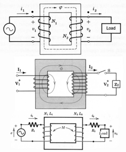
Shouldn't the diagram take into account an inversion of voltage polarity in the secondary winding, relative to the polarity of the voltage that is applied in the primary? As I see it, in the way that the secondary is wound: 1. conventional current should flow in the direction depicted, ok. But, 2. The voltage "arrow" should be pointing down (that is, there should be a "+" voltage sign in the bottom wire, and a "-" sign in the top wire). This is what would make current flow in the direction shown in the diagram when a circuit is actually connected to the secondary (according to Lenz's law, which by the way isn't even mentioned in the whole article). Am I missing something? --Cbohorquezm 20:30, 14 August 2006 (UTC)
- If you agree that (conventional) current flows from top to bottom on both sides, then surely you must also agree that the top wires are at higher voltage than the bottom wires on both sides...? Not sure why you bring up Lenz's law, since that only determines which direction the current flows, and we agree on that point.. Pfalstad 23:10, 14 August 2006 (UTC)
My doubt is about the polarity or phase of the output voltage of the secondary, considering the depicted conventional current direction. For (conventional) current to actually flow in the secondary there has to be a closed circuit on that side. Let's say you connect a resistor. If conventional current flows "out" through the "top" of the resistor and then flows "in" the transformer through the top wire (as shown), this conventional current should've been injected through the "bottom" of the resistor, that is, through the bottom wire. Meaning that the highest voltage level should be in the bottom wire..and the "+" sign, or the arrowhead, should be at the bottom...right? --Cbohorquezm 02:59, 15 August 2006 (UTC)
- Right.. Sorry, brain not working.. Pfalstad 03:10, 15 August 2006 (UTC)
To summarize then, the EMF depicted in the secondary is wrong, and it should be inversed. Can someone please edit the image?--Cbohorquezm 15:31, 22 August 2006 (UTC)
- No, the diagram (as of my typing this) is correct. Use the right-hand rule and you'll see that the current in the primary is producing MMF (and so resulting flux) in the clockwise direction. Any current flowing in the secondary coil would produce an opposing MMF tending to circulate flux in the counterclockwise direction (facing the diagram), which is correct. --Wtshymanski 17:40, 22 August 2006 (UTC)
I know the direction of the current in the secondary is correct....I'm referring to the voltage of the secondary, specifically to its polarity or phase, which appears to be inversed (Pfalstad seems to agree with me). If a resistor is connected to the secondary, and a voltage of the polarity shown is applied to it, the current would flow from the bottom to the top of the secondary. Since we know that this is incorrect and that the current MUST flow from top to bottom through the secondary coil (as shown in the diagram) then the voltage polarity must be inversed (the arrow should be pointing down, and not up). This polarity will ensure that, when a load is connected, the current will have the appropriate "direction" (which in fact represents the phase of the current). That is, the direction of the current shown in the diagram.
And to further elaborate, the phase of the voltage in the secondary cannot be dependent on the presence or lack of a load connected to its terminals, right?
I'd like to know the point of view of more people about the phase of the voltage in the secondary, since the two answers yet have only mentioned the direction of the current, which I agree is correct, but have not referred to the phase of the voltage required to create that current--Cbohorquezm 01:47, 23 August 2006 (UTC)
- If the tip of the arrow is positive, and there is no external source driving the sec current, then the direction of the sec voltage appears to be shown incorrectly.--Light current 01:59, 23 August 2006 (UTC)
- I agree with you about the voltage having the wrong phase, yes. The text you quoted below was a bit confusing.. Don't think it's relevant here, and the diagram has changed since then. Pfalstad 04:21, 23 August 2006 (UTC)
Removed quote --Cbohorquezm 16:07, 23 August 2006 (UTC)
- Don't think so: doesn't matter if the tip is positive or negative (it'll change a half-cycle later anyway) but in both primary and secondary the two arrows are consistent. --Wtshymanski 17:29, 23 August 2006 (UTC)
- Sorry, dont both the primary arrow set and the secondary arrow set show power/energy entering the transformer? How can this be?--Light current 19:10, 23 August 2006 (UTC)
Exactly...It would be good if Wtshymanski could explain why "in both primary and secondary the two arrows are consistent". And the affirmation that the phase will change "anyway"...yes, but what's important is not the instantaneous phase (which will of course change every half-cycle), but the phase of voltage in the secondary relative to the other voltages/currents of the transformer. I think Light Current's question is very good, and it illustrates the point of the diagram being wrong. The opinion of more people would be really appreciated.--Cbohorquezm 03:45, 24 August 2006 (UTC)
- The EMF arrow is pointing at the same terminal at which the current arrow is pointing, is what I meant by consistent. By all means, let's get more opinions, then we can vote on the way transformers work instead of dragging the article down with references and facts 'n'stuff. --Wtshymanski 22:03, 24 August 2006 (UTC)
- Yes BUT, the windings are wrapped in the opposite sense to one another. Do you agree?--Light current 01:08, 25 August 2006 (UTC)
- Here are some votes by way of text books containing diagrams that are consistent with the diagram as is is:
- Fitzgerald, A. E. (1983). Electric Machinery (4th ed. ed.). Mc-Graw-Hill, Inc. ISBN 0-07-021145-0.
{{cite book}}:|edition=has extra text (help); Unknown parameter|coauthors=ignored (|author=suggested) (help) - Gehmlich, Dietrich K. (1967). Electromechanical Systems. Mc-Graw-Hill, Inc.
{{cite book}}: Unknown parameter|coauthors=ignored (|author=suggested) (help) - Smith, Ralph. J. (1971). Circuits Devices and Systems (2nd ed. ed.). John Wiley & Sons, Inc. ISBN 0-471-80170-4.
{{cite book}}:|edition=has extra text (help); Cite has empty unknown parameter:|coauthors=(help)
- Fitzgerald, A. E. (1983). Electric Machinery (4th ed. ed.). Mc-Graw-Hill, Inc. ISBN 0-07-021145-0.
- The diagrams in these texts are different in that the secondary winding is a mirror image of the primary. --C J Cowie 23:22, 24 August 2006 (UTC)
- Here are some votes by way of text books containing diagrams that are consistent with the diagram as is is:
- So they're not consistent with the diagram as is? If the secondary winding is in the opposite direction? Pfalstad 02:48, 25 August 2006 (UTC)
- I really hate to drag this up again 8-), but the secondary current direction as shown produces a flux in an opposite direction to that shown in the core. Yes?--Light current 01:04, 25 August 2006 (UTC)
- The current in the secondary is not producing a flux. The flux is producing a current in the secondary. The primary is like a load, and the secondary is like a source.
- And yes, the voltage arrow on the secondary is upside down and wrong. — Omegatron 02:51, 25 August 2006 (UTC)
- I fixed the image. — Omegatron 03:12, 25 August 2006 (UTC)
Perfect! It was really great to see the improvement being discussed and finally being implemented. Thank you all. --Cbohorquezm 04:07, 25 August 2006 (UTC)
- I agree. I got engrossed in the current and flux directions and missed the problem with the voltage polarity of the secondary. --C J Cowie 12:18, 25 August 2006 (UTC)
Images
Please double check these similar images:
-
 Secondary voltage wrong direction (fixed)
 -
 Secondary voltage wrong direction (fixed)
 -
 Secondary voltage wrong direction (fixed)
 -
 Secondary current wrong direction (fixed)
 -
 Secondary voltage and current both wrong direction (fixed)


But wait a second... The secondary voltage was obviously not consistent with the current arrow for a source of energy, but let's go back to the current for a second:
According to Lenz's law, the induced current from a changing magnetic field is in a direction that opposes the change. So as the magnetic field is increasing, the current would flow in one direction, but as the magnetic field decreases (still pointing in the same direction), the current would then switch directions? Is this right? So the current in the secondary will be 90 degrees out of phase with the primary? I don't think that's right, but if it is, the secondary current arrow can be in either direction, depending on whether the field is increasing or decreasing. — Omegatron 14:05, 25 August 2006 (UTC)
- No, the two currents are in phase. Let me attempt to explain why. Let's say we apply a steady current to the primary of an ideal transformer.. This creates a flux.. The flux causes current in the secondary.. The current in the secondary creates an opposing flux that cancels the original flux. LC will tell you that the flux in an ideal transformer is zero. I think that the flux is positive when the primary current is increasing and negative when it is decreasing. It's not proportional to the primary current. Pfalstad 14:50, 25 August 2006 (UTC)
No, a steady DC current would create a flux, just like an electromagnet, but the constant flux would not create a current in the secondary. Currents are only induced by changing magnetic flux. If the flux direction changes as the current increases or decreases, that would make sense, but I don't think that's the case, either. This seems like pretty simple stuff, but I'm confused. — Omegatron 15:30, 25 August 2006 (UTC)
- It does change. It starts at no current/flux and then changes to a steady current/nonzero flux. :) Pfalstad 19:00, 25 August 2006 (UTC)
Sure, but what happens when it starts at a steady current/nonzero flux, and changes to no current/flux? The flux and primary current will be in the same direction all along; does the secondary current go in the opposite direction to oppose the changing flux? The "opposes a change in flux" part makes it sound like the secondary will be a derivative function of the primary, but I don't think that is the way it works, or I would have heard it before. — Omegatron 19:24, 25 August 2006 (UTC)
- The flux is zero if the current is not changing, in an ideal case. The secondary current will resist any changes in flux--any attempt to make the flux nonzero. So, the flux and primary current are not necessarily in the same direction. The flux is in the direction of the first derivative of primary current, I think. You can verify with a simulator that the primary and secondary currents are either in phase or 180 degrees out of phase. Pfalstad 20:35, 25 August 2006 (UTC)
That makes a little more sense. In an ideal transformer, can DC be transmitted from primary to secondary? — Omegatron 20:56, 25 August 2006 (UTC)
- Think so, see [4] under "Ideal Transformer". Sorry, don't have any decent references. Pfalstad 00:40, 26 August 2006 (UTC)
- Yes, but not for an infinite period, only for 0.999... of the time ;-).
- Atlant 17:06, 27 August 2006 (UTC)
- All DC is ultimately AC unless the DC has been there for ever.
That's very important, though, and nothing I ever heard before. Ideal transformers carry everything from DC to light, but real ones have parasitic components that filter out other frequencies. Very interesting concept. Is the ideal transformer consistent with Maxwell's equations? And real life transformers just don't confine the flux completely and have non-zero resistance and all that? Could it be realized with superconductors and superpermeable(?) core or something? — Omegatron 19:23, 27 August 2006 (UTC)
- Should we cover questions like this in the article? Comparison between ideal and real transformers? I never knew that an ideal transformer passed DC until this discussion. — Omegatron 13:52, 3 September 2006 (UTC)
- This article doesn't explain what an ideal transformer is or the purpose. It jumps right into a bunch of their properties with no mention of purpose or signifigance. In my experience ideal cases were used to simplify analysis; this article seems to complexify it. When you learn RLC circuits for instance you don't have to worry about the resistance of the wires connecting everthing or the inductance in a resistor or the internal resistance of a battery.
- Could the ideal transformer be a new article? Are there more than one reliable sources that agree on the DC passing issue? -Crunchy Numbers 18:42, 4 September 2006 (UTC)
Transformer as typically presented in engineering texts

Transformer diagrams as presented in reference texts listed above. Forgot to sign. --C J Cowie 16:23, 25 August 2006 (UTC)
Here's the version from my book: [5] They're all consistent with each other and with the diagram after my changes. — Omegatron 16:48, 25 August 2006 (UTC)
- Yes they are all consistent with each other. Note that the top one of those I provides shows the dot marking that is often used by manufacturers to idicate the phase relationship between the windings. --C J Cowie 17:10, 25 August 2006 (UTC)
Of course you mean polarity relationship. ;-) — Omegatron 18:36, 25 August 2006 (UTC)
- Interesting point. User:Crunchy Numbers just edited the article to say the dots indicate phase relationship. Fitzgerald et al uses terms "corresponding polarity, "same instantanious polarity" and [voltages and currents] "are in phase." Hammond refers to "winding sense." --C J Cowie 19:18, 25 August 2006 (UTC)
See Talk:Phase (waves)#Phase vs polarity. :-) — Omegatron 19:27, 25 August 2006 (UTC)
- Good point, I shouldn't have said phase. My circuits book says the dot notation takes care of different relative winding configuration. The line I edited implied that the dot was about physical proximity.-Crunchy Numbers 19:56, 25 August 2006 (UTC)
- It seems to me this article is way too detailed for an encyclopedia for lay people. Engineers and students should look at their textbooks and references not here. The average person doesn't need the formulas for flux and voltage or need to know that the windings can have different configurations. Most people haven't had the math for that.
I think the article should concentrate on things like the turns ratio and talking about how ac allows high voltage power transmission over long distances with low losses as compared to DC. Maybe a blurb about the special properties of sinusoidal waveforms but in a general way. The stuff about how a transformer won't work with DC is great, can go with something about changing magnetic flux is needed.
So far I have seen people quoting Lens without seeming to understand a simple resistor inductor circuit or knowing about Kirchoff's laws. Just my two cents. Or the EE stuff could go into some other articles -transformer formulas- with a warning for non techies to stay out ;)
This is not an encyclopedia for laypeople; it's an encyclopedia for everyone. Also, wiki is not paper. There's absolutely no reason to remove relevant information. There are, of course, reasons to split articles into smaller pieces (which this article needs) and to write introductory material that's understandable to the lamest of laymen. I think the article does pretty well on that point, with the gear box analogy, etc.
When we split it into smaller articles, can we please divide them in a sane, logical way? We need to decide on the talk page what to split it into first, and then, when a consensus is reached, start doing the splitting. (I am, of course, thinking of Capacitor, Capacitor (component), and Capacitance when I say this...) — Omegatron 20:45, 25 August 2006 (UTC)
- I think that is a good point. However there is some value in providing a more than a basic level for people who are capable of understanding more but are not actually students and don't have free access to text books. In the USA, text books are pretty widely available in libraries including the interlibrary loan system and older editions are fairly inexepensive on eBay, but I think Wikipedia is trying to be an option for those that have internet access but not oother good options. I have seen some discussion about splitting articles into basic and advanced sections to make them more usable at multiple levels. --C J Cowie 20:36, 25 August 2006 (UTC)
- Good point about people without access to libraries or books.
But I can imagine a kid in 6th grade doing a science project about transformers and seeing this article. He would probably give up. The encyclopedia was a big thing to me growing up before the internet was available. The problem with the net is too much. Too much detail, too much crap, too many conflicting viewpoints from well meaning but misguided folks. This article seems to me like a class where the students are changing the book while the professors aren't looking.
- btw, The statement -The flux is zero if the current is not changing, in an ideal case- is not true. Induced current in a secondary winding depends on change in flux which isn't there for dc. But without flux a dc motor wouldn't work.-Crunchy Numbers 20:54, 25 August 2006 (UTC)
- How sad 8-( I have missed all this interesting discussion whilst on Wikiholiday. Anyway it seems you all got on fine any how and the diagram is more correct now. The question of flux or no flux in the core of an ideal transformenr however remains.--Light current 17:40, 30 August 2006 (UTC)
Page splitting
When Omegatron said:
When we split it into smaller articles, can we please divide them in a sane, logical way? We need to decide on the talk page what to split it into first, and then, when a consensus is reached, start doing the splitting. (I am, of course, thinking of Capacitor, Capacitor (component), and Capacitance when I say this...) —
Did he mean that the capacitor thing was not done right? --Light current 17:59, 30 August 2006 (UTC)
- Yes. — Omegatron 03:43, 28 November 2006 (UTC)
3 ph from 2 ph
Dear Sirs,
Is it possible to power a three phase condensor unit, atop a building supplied with two phase power?
Sincerely, Sergei
- I think you need to ask this question on the Wikipedia reference desk--Light current 02:44, 27 May 2006 (UTC)
- If its true two phase then yes it should be possible with a couple of transformers. If its split phase (more likely) then you'll need a single to 3 phase converter of some kind (which exist but don't come cheap). Plugwash 15:36, 5 June 2006 (UTC)
- As Plugwash suggested, true two phase (90 degree phase difference) can be converted back and forth with true three phase (120 degree phase difference) using a Scott-T Transformer.
- Atlant 15:52, 5 June 2006 (UTC)
An analogy
Hi Light current. I know that I've moved the "analogy" section before, but please don't think that I'm persecuting you. I had to move it because your last edit resulted in a non sequitur, with the analogy immediately followed by the second half of the overview, but no "end of analogy" warning. Evidently our opinions differ on where to put the analogy, but I won't revert your next move as long as the article remains consistent. --Heron 09:19, 27 May 2006 (UTC)
- Yeah I thought the analogy was better in the overview rather than in the nitty gritty details of the electrical explanation.. I will take more care to make things follow properly before moving it again. 8-)--Light current 16:50, 27 May 2006 (UTC)
The analogy now incorporates reference to gear box, gear ratio. It was changed substancially. I was never a friend of it. But the way it is now, i do not find a serious reason to remove it etc. I just do not require it personally. A month ago, it was spelled in over-complicated language. Yy-bo 19:26, 4 June 2006 (UTC)
- Thank you (I think!)--Light current 19:27, 4 June 2006 (UTC)
Half wave recs and dc in sec.
I hadnt realised that Atlant! so good edit. Yes, rectifiers are usually a nuisance to the power companies! 8-)--Light current 17:43, 1 June 2006 (UTC)
Hysteresis and reluctance
Im rather reluctant to suggest this and do not want to cause any hysterics, but does anyone think that one or both of the diagrams below should be incorporated into the page? 8-))--Light current 02:25, 3 June 2006 (UTC)


Actually I think the curve starting at the origin in the LH diag should not be parallel to the major loop curves but should bend over to the right earlier and meet the other two curves at their intersection --Light current 17:01, 3 June 2006 (UTC)
- This article doesn't need to replicate the hysteresis article. Add too much explanation and you'll find that to understand transformers is to understand the sum total of human thought to date. Wikipedia articles should *focus* and not ramble on every possible relationship between the putative subject and the rest of the known universe. --Wtshymanski 18:44, 3 June 2006 (UTC)
Page split?
I agree. The article is way too long as it is. Focus! Pfalstad 06:01, 6 June 2006 (UTC)
- Ok suggest how to split it. 8-|--Light current 14:00, 6 June 2006 (UTC)
Copied from start of page:
== possible split up of the article ==
- transformers
- physical principe
- scope of application
*transformers_(iron_core) (new article)
- power grid transformers (low power)
- signal transformers
- power transmission transformers
*transformers_(ferrite) (new article)
- power supply transformers
- flyback transformers
- filters (reference)
*transformers_(special) (new article)
- isolation transformer
- voltage transformer
I wouldn't divide it up that way. I would take the construction portion and move it into a separate article; and I would take most of the items under "Transformer designs" and move them to separate articles. Pfalstad 14:19, 30 April 2006 (UTC) copied by --Light current 15:04, 6 June 2006 (UTC)
Still irked
The "alternative analysis" still troubles me and I think it is in fact wrong. As I've always seen it described, the primary and secondary MMFs don't cancel in the mathematical sense. The primary MMF is negligably small assuming a very large permeability of the core, but it is *required* in order to sustain flux in the core. You must have flux else there's nothing to change and so voltage across the winding. Secondary current produces an opposing MMF, so primary current must increast to provide the ampere-turns required to sustain the flux. It all comes of trying to divide by zero. It would be better to think of the "ideal" transformer as being the limiting case as permeability heads toward "infinity", which is a term that always causes trouble in an engineering context. --Wtshymanski 18:31, 10 June 2006 (UTC)
- The alternative analysis is incorrect. For the ideal transformer, the permeability of the core is infinite. When this is the case, H cannot exist in the core for if it did, B would be be infinite. Without any H in the core, the mmf of the primary and the secondary must exactly cancel. However, and this is where the alternative analysis section get its wrong, zero mmf does not imply zero flux. In the ideal core, flux exists without mmf. Interestingly, the 'other' characteristic of an ideal transformer - zero leakage flux - is unaffected by the ideal core. To achieve zero leakage flux would require surrounding the core and windings with material that has zero permeability. Alfred Centauri 19:55, 10 June 2006 (UTC)
- Let us therefore change the wording in accordance with the sentiments of the above 2 posts!--Light current 01:12, 11 June 2006 (UTC)
- Aha! Is that the hidden message in Alfreds earlier exposition: that transformes can only work if they are in a medium with non zero premeability>? This seems obvious now but wasnt before!--Light current 01:20, 11 June 2006 (UTC)
Transformer vector group
What is the basis of selection of Vector Group while making the selection of Transformers?
- That's a very general question. If you want two transformers to operate in parallel, you must have the same relationship in phases between primary and secondary terminals. If you wish to create a neutral for a distribution system, you must choose a transformer with a winding that has a star point. If you're dealing with multiple DC rectifiers, you may alternate vector groups in order to create less harmonic distortion on the primary system. ( And you can sign your posts with --~~~~) --Wtshymanski 17:39, 21 June 2006 (UTC)
I thought you could make an artifical neutral on a delta connected system by using a star connected trans with the star point giving you the neutral. I think theres a special name for this trick. 8-)--Light current 18:02, 21 June 2006 (UTC)
- That's no longer an "artificial neutral" since it will allow zero sequence currents to flow. Where it's desirable to provide a grounded neutral for a system without sourcing zero-sequence current, you will find a zig-zag transformer ( guess no-one's written that article yet) to provide a neutral without letting fault currents flow phase-to-ground. --Wtshymanski 17:57, 22 June 2006 (UTC)
Yes thank you. Its a zig zag transformer I was thinking of. THanks for the correction! 8-)--Light current 22:33, 22 June 2006 (UTC)
Impedance matching
I don't know tube amplifiers very well, but I know of no audio circuitry besides telephones that use impedance matching. In everything, microphone→preamp, circuit→circuit, and amplifier→loudspeaker, the output impedance is low and the input impedance is high. Transformers can be used to create the desirable impedances, but the impedances are not "matched" or made equal. — Omegatron 20:06, 25 July 2006 (UTC)
- I agree, but there are lots of misconceptions out there. Hyperphysics seems to think that impedance matching still rules in audio. I think that's just plain wrong. Here's a publication that knows what it's talking about: Electus Distribution Reference Data Sheet - Impedance Matching: A Primer (PDF). It mentions the case of some pickups and microphones that require the correct load to provide damping, which is kinda sorta impedance matching, but not in the sense in which that phrase is normally used. --Heron 20:58, 25 July 2006 (UTC)
- I've written to HyperPhysics several times about that page. No response.
- And yeah, I put a section into impedance matching explaining that some people use "impedance matching" to mean "connecting a low output impedance to a high input impedance", since you're "matching" the two to each other for best performance. Similar to how you "match" a mic element to a load for the best sound, but it's not "impedance matching" in the traditional sense (or is it? What was the original meaning of the phrase?)
- There are some further references on Talk:Impedance_matching#Sanity_check from January. — Omegatron 21:13, 25 July 2006 (UTC)
- I suppose there's always an exception to the rule and in this case it is that Nelson Pass has introduced a couple of power amps that have a (relatively) high output impedance - about 100 ohms. He has some papers on the website about the benefits of driving certain loudspeakers with a current source: [6] Alfred Centauri 12:47, 26 July 2006 (UTC)
- Yes current driving of loud speakers can be very advantageous. See damping factor under zero electrical damping. Yes, this would be a case of bad matching in the electrical sense, and so leads to inefficiency; but the complete system benefits (ie small cabinet and linear cone movement) are IMO worth having.--Light current 13:11, 26 July 2006 (UTC)
- I imagine there are exceptions, but in most cases it is not used. Here is another article about current driven loudspeakers, saying that voltage drive is better in the vast majority of cases.
- Driving a loudspeaker with a current source is not a case of impedance matching, anyway. The only reason I can think of that impedance matching would be used (making source and load resistance equal) is in audio distribution systems with long wire runs (but they'd have to be a few kilometers away from the amp, right?), or some aspect of tube amp outputs that I don't have experience with. — Omegatron 13:39, 26 July 2006 (UTC)
- Yes Ive seen that one too. I agree that, generally, driving a loudspeaker with a current source is not a case of impedance matching, its is rather a case of deliberate mismatching. For max efficiency, the amp o/p would need to be matched to the 'effective' impedance of the LS (ie including the cabinet and air loading).
- Its a question of horses for courses. Voltage drive is better with ported cabs except there is little control of cone movement below resonance due to less than ideal damping, Current drive appears to give flatter LF response with sealed cabs. In this case, cone movement is resisted over the whole frequency range by the non infinite compliance of the air in the box amnd therfore a more linear motion of the cone is obtained than can be achieved with vltage drive below resonance.
- So you must pay your money and take your choice! 8-)--Light current 15:36, 26 July 2006 (UTC)
- For maximum efficiency into a fixed load impedance, you want the source impedance as low as possible. For a given fixed source impedance, you make the load impedance equal for maximum power. I believe this holds regardless of whether the power is being converted to different forms.
- Regardless, the point of this discussion is whether transformers are used for impedance matching in audio, and none of us has come up with a situation in which they are. — Omegatron 17:44, 26 July 2006 (UTC)
- Yes Im sure they used to be used (normally attached to the LS itself) for 100v line work. Or are you saying th6ts not Z matching but just volume control?--Light current 17:55, 26 July 2006 (UTC)
- But that's not impedance matching at all, is it? That's just impedance conversion. It's not matching unless it's being used to make the load impedance equal to the source impedance, for loss of reflection or maximum power.
- We need an article on constant-voltage audio distribution.[7] — Omegatron 18:32, 26 July 2006 (UTC)
- For tube amps, it looks like the tube output wants to see a certain large impedance, like 5 kΩ, so you select an output transformer to make your 8 Ω loudspeaker look like a 5 kΩ loudspeaker, "matching" it to the optimal load for that tube. I think this is another loose usage of the word "matching" and isn't an attempt to make the load equal to the source for reflections or maximum power. — Omegatron 18:48, 26 July 2006 (UTC)
- Earlier, Omegatron, you asked what might be the original meaning of the phrase. Suprisingly, the OED defines it:
- impedance-matching, the adjustment of impedances in such a way as to minimize the power reflected or the reduction in the power transferred that occurs when an oscillatory current or other wave meets a change in impedance"
- and the earliest citation is from 1929, talking about the max power theorem. I wouldn't trust the OED to know the current usage of the term, but they ought to know about its history. --Heron 18:05, 26 July 2006 (UTC)
Transformers: ratings
I read the article about transformers a few months ago and then I started to think about ratings. A few years ago I had to build a stereo and I wrote a report on it. The voltage from the socket was 120V AC RMS at 60Hz and the power amplifiers needed ±35V DC.
This is taken from my report:
"The power requirement for this application is ±35V DC and the only source of power available is 120V AC at 60Hz. In order to get the proper voltage, a 70VA/90VA, a centered tapped transformer will be used to reduce the 120V AC signal to a 50V AC signal. The frequency of the signal remains constant. This voltage feeds the power supply, which changes the AC signal into a DC signal. The result is a ±35V DC signal to be used for component power."
I was trying to understand how to to get from 120V AC RMS at 60Hz (socket side) to ±35V DC (power amplifiers side) when I realized that I forgot what 70VA/90VA means and that I don't even know if that figure is correct.
I would like to know what is the logic. If any of you knows it, please explain it to me.
1. If you have X voltage at the socket and Y voltage for the power amplifiers how do you calculate what rating you need?
2. What does 70VA/90VA exactly mean?
3. Is it imperative to talk about RMS voltage on the primary and secondary side?
This is my first time posting on Wikipedia. I leave my e-mail in case somebody reads my post. If it is not legal I apologize for the inconvenience right now and I will remove my e-mail as soon as possible. If you really know about this subject please let me know what you think. Please be clear and specify if you are talking about peak or RMS voltage.
ICE77 -- 84.222.103.223 07:05, 18 August 2006 (UTC)
- Transformers have two critical ratings:
- Their voltage ratio (from primary to secondary), and
- The amount of power they can pass through them without overheating
- I think you're confusing these two parameters a bit.
- "VA" (Volt-amperes) is the measure of how much power you can pass through the transformer. You can usually think of this as "Watts", but VA is more technically correct because it accommodates the concept of power factor. So if your load was ±35V (70V total) at, say, 2 Amps, you'd need a transformer with a rating of at least 140 volt-amps.
- Then there's the question of the voltage ratio. What you probably really want is ±35V DC minimum. AC voltages are usually specified in terms of their RMS voltage, but rectifiers actually capture the peak voltage, at least when they're lightly loaded. So to get 35 volts DC, you need something like 35/1.414 (the square root of 2) = 25 volts RMS going into the rectifier. To get bipolar voltage (±35V), most people would use a center-tapped transformer and a full wave bridge rectifier, so you'll need a transformer with an output voltage of about 50 volts and a center-tap on that winding.
- In fact, you'll need a bit more voltage because under realistic loads the rectifier/capacitor stage won't quite achieve 1.414 times the RMS voltage as its DC output voltage. But how much it "droops" depends on a lot of stuff including the size of the filter capacitors, the amount of peak current you'll allow, and such like.
- Does all of this help you? ;-)
- Atlant 13:26, 18 August 2006 (UTC)
Atlant, thank you for explaining some of the points about transformers. Now I am starting to get a sharper picture of the basic concepts.
If I understand correctly, correct me if I'm wrong, transformers are practically always rated in RMS, so in my case I had 115V AC RMS on the primary and most likely 50V AC RMS on the secondary (±25V RMS and center-tapped).
The secondary was feeding a bridge rectifier to produce 70V DC peak for the power amplifiers (±35V DC peak and center tapped). The jump from 25V AC RMS to 35V DC peak is produced by a bridge and it's justified by the nature of the diodes/rectifiers that make it up. Basically, 25 is multiplied by 1.414 and it becomes 35 because the 4 diodes make a full-wave rectifier and average the positive waves produced by the bridge itself.
The output of the bridge goes through center-tapped capacitors to smooth the output to +35V DC peak (only the positive output of the bridge is used). The signal is then fed into the power amplifiers which should be supplied by a maximum of +35V DC (me and my buddies burned some power amplifiers previously because we supplied them with +47V).
If the logic is correct, this is what I think I had in the circuit. I hope this makes sense to you. Please let me know. I troubles me a lot not to understand the logic going step by step (I guess you can tell).
Now, looking at the 70VA/90VA, I understand it has to do with the concept of power which can be measured in W, but since we consider a factor it should be VxA. Based on this considerations, 70VA/90VA is still not clear to me because I don't understand if that number applies to secondary only of it is a ratio between primary and secondary. If that number is for secondary only I would imagine that 90 is a maximum number for the transformer, a way to add some safe buffer zone for the operation of the transformer. If it applies to primary and secondary then it makes less sense. Please explain this to me.
ICE77 -- 84.222.102.209 18:21, 21 August 2006 (UTC)
- Let me try to cover all of the points you raised:
- Yes, power transformers are always rated in terms of RMS voltages because we're almost always dealing with (close-enough-to-)sinusoidal power waveforms and RMS is the handiest measurement "style" until you hit that pesky rectifier stage.
- The DC that comes out of the rectifier is (roughly) equal to the peak, not RMS value of the sine-wave because it is only at the peaks of the sine wave that current actually flows through the rectifier diodes from the power transfomer into the bulk-storage capacitors. If you could put a current probe on the transformer, you'd see these very large pulses of current that are synchronized in time with the tips of the sine wave. The rest of the time, the capacitors are discharging into the load as they attempt to maintain the output voltage until the next current pulse comes along and recharges them.
- The VA rating of a transformer can be thought of as the maximum amount of power that can flow through the transformer from the primary to the secondary/secondaries. Roughly speaking (ignoring the slight inefficiencies in a pretty good power transformer) , the maximum VAs you will see in the primary winding is equal to the VA rating of the transformer as is the sum of the VAs in all the secondary windings. To make the numbers easy, let's take a hypothetical 120VAC-to-12VAC transformer rated at 120 VA. At full rated power flow, the primary will have 1 Amp of 120 VAC power flowing in it for 120 VA. The secondary will have 10 Amps of 12 VAC power flowing in it for the same 120 VA. If we instead had two 12 VAC secondary windings, you might see (for example) 5 Amps in one and 5 Amps in the other for a total that is still 120 VA in the sum of all of the secondary windings.
- And again, just to drive the point home, whatever wattage you're hoping to get out of your audio power amplifiers, the transformer will have to have substantially more VA than that, because you'll lose power (into the form of heat) at various stages in the amplifier system. The rectifier loses a little power, the power transistors in the output stage lose a lot of power, the various driver stages in the amplifiers essentially are total power losses, etc. So a hypothetical 70 VA transformer will probably put out about 35 Watts total RMS audio power at best.
- Atlant 18:42, 21 August 2006 (UTC)
Atlant, thank you for responding once again. I read your short biography on Wikipedia and I was impressed by your experience and your knowledge.
When we talk about transformers RMS voltage over peak voltage is the standard. I will keep that in mind.
The point you are trying to make about the output of the bridge rectifier was quite clear to me already. I don't understand why you explained that, but that's fine, it was a good review.
Wattage considerations are also clear now. Based on your considerations, I could say that in a circuit it is a good idea to double the wattage requested by the power amplifiers in order to come up with the power factor for the transformer we need to use. I'll keep that in mind. Transformers are like cars ... there are not very efficient!
The example you made for the 120VAC-to-12VAC at 120VA transformer was also clear to me already (VAC is alternating current voltage and VA is power factor) . The idea is that power in the primary must equal power in the secondary and that the power factor is a constant for primary and secondary. In other words, as we know, energy cannot be distroyed nor created. If there is one secondary only, the current in the secondary will be higher to match the power in the primary. The only point that still puzzles me is that I wrote 70VA/90VA and I still don't understand what 70VA and 90VA refer to, especially in the circuit I described previously. I wonder if 70VA was an average power factor and if 90VA was a maximum power factor for the transformer. Please try to explain it to me. I'm not sure you understand what I don't understand.
ICE77 -- 84.222.102.61 14:33, 24 August 2006 (UTC)
Travel adaptors
I got out my travel adaptor that says that it is not to be used with electronics. Why would this be? My guess is it's just a transformer and a fuse that drops 220 volts to 110 volts. Could there be something else in there? --Gbleem 17:52, 24 August 2006 (UTC)
- High-power travel adapters don't contain transformers. They use a variety of techniques to pulse width modulate the 230 VAC down to an average value of 120 VAC, but the pulses are still 230 VAC and will fry many electronic devices. The "50 Watt" (and lower) travel adapters tend to be real transformers; you can also identify them because they're typically "transformer-heavy".
- Atlant 18:53, 24 August 2006 (UTC)
'The' diagram
Caption says its a step down. But it could equally well be a step up. Can we remove the qualifier 'step down' from the caption?--Light current 18:04, 30 August 2006 (UTC)
- How could it possibly be a step up? You can count the number of turns as well as I can. — Omegatron 03:53, 28 November 2006 (UTC)
- You could turn it round! I think at one time the primary and sec were not labelled and so it could have been either. But as shown now, it is a step down device. 8-)--Light current 03:55, 28 November 2006 (UTC)
- Primary and secondary have always been labeled. You can look through the various revisions yourself, just as you can look through the revisions of an article. Here's how it looked in January 2006, for instance. — Omegatron 04:42, 28 November 2006 (UTC)
- And of course it depends on how you define the words 'primary' and 'secondary'. In fact many transformers are commonly used backwards! 8-)--Light current 04:53, 28 November 2006 (UTC)
How else would you define the words 'primary' and 'secondary'? They are unambiguous in meaning:
- Primary
- Electronics. Of, relating to, or constituting an inducting current, circuit, or coil.
- Electronics. An inducting current, circuit, or coil.
- First winding of a transformer. Winding that is connected to the source as opposed to secondary which is a winding connected to a load.
- coil forming the part of an electrical circuit such that changing current in it induces a current in a neighboring circuit
- A primary winding; the driven winding of a transformer
- Secondary
- Electricity. Having an induced current that is generated by an inductively coupled primary. Used of a circuit or coil.
- Electricity. A coil or circuit having an induced current.
- Output winding of a transformer. Winding that is connected to a load.
- coil such that current is induced in it by passing a current through the primary coil
The primary is the side driven by a source and the secondary is the side with the load. If you used it backwards, you'd also have to change the "primary" and "secondary" labels. The primary and secondary are labeled, so this is a step-down transformer, unambiguously. — Omegatron 00:02, 29 November 2006 (UTC)
analogy of transformer with motor
its very interesting to get article on why transformer doesnt tend to rotate? its principle and theory is expected.
- You tell us why you think it should rotate, and we'll tell you why you're wrong. Your answer is expected. --Heron 10:05, 3 September 2006 (UTC)
But you can have rotary transformers cant you?--Light current 01:03, 8 September 2006 (UTC)
Toroidal o/p transformers
Im just wondering why toroidal transformers with, say, bifilar windings do not seem to be used as o/p transformers in audio amps. Can anyone think of a reason?--Light current 23:51, 4 September 2006 (UTC)
- What's an "output transformer"? ;-) Haven't seen one of those in ages and ages!
- Atlant 23:55, 4 September 2006 (UTC)
Something that, I believe, was used in pre history for matching the impedance of those funny glowing bottles to the speaker!.--Light current 23:59, 4 September 2006 (UTC)
- I guess valve guys are traditionalists and transitor guys worked out some time ago that with complementry output stages and either a split rail supply or a bridging arrangement you don't need output transformers.
I know you don't for transistor designs. I was wondering why they werent/arent used for valve audio designs.--Light current 00:48, 8 September 2006 (UTC)
- I assume it was just because the transformer guys didn't yet have automated winding machines for toroidal transformers or the cost/benefits trade-offs weren't attractive enough compared to good old bobbin-on-core transformers.
- Atlant 01:47, 8 September 2006 (UTC)
Ok. Well theres a market niche! Expound the benefits of toroidal transformers to make your valve amp sound even better!! You could become a millionaire overnight! Audiophiles will pay anything for new ideas.--Light current 01:51, 8 September 2006 (UTC)
- http://www.plitron.com/audio.asp
- How do they wind toroidals, anyway? Sounds like an interesting topology problem... — Omegatron 03:34, 28 November 2006 (UTC)
- Not really. THe wire is first wound onto a shuttle (weaving) which is passed throgh the hole in the centre. I think there are m/cs to do it. Its a bit like weaving! If you wanted to do it by hand, you could get hold of a popsicle stick, cut a groove in each end, and wind the wire round it to act as your loaded shuttle. 8-)--Light current 03:48, 28 November 2006 (UTC)
From the article: Audio frequency transformers, (at the time called repeating coils), were used by the earliest experimenters in the development of the telephone.
- I originally edited this line because the phrase "at the time" or "then" comes before any reference to when or at what time. It sounds confusing because the reader can't be sure if the time is during the developement of the telephone or some other time before that that was established in an earlier sentence.
- After that was reverted I followed the repeating coil link and found that the term still seems to be used. That seemed to me to make the "then" clause unnecessary so I removed it. That got reverted.
- I don't understand what was wrong with my edits or what is so special about the original phrasing. -Crunchy Numbers 16:54, 8 September 2006 (UTC)
Edit by 63.23.18.109
Light Current, you should have reverted that last one by 63.23.18.109. They broke some links and added added a little how to with old transformers. I was in the process and got called away before I saved and then you edited something. -Crunchy Numbers 23:52, 22 September 2006 (UTC)
- Sorry didnt spot it! 8-( You are welcome to revert back over my changes!--Light current 00:10, 23 September 2006 (UTC)
Article length
Before adding great slabs of data to the article, please read Wikipedia:Article size and consider that right now only a lunatic would read to the end of this article as it stands. A big numeric table is only interesting to the 5 or 6 people in the world who actually design anything - the general reader won't benefit from a minute comparision of 32 different alloys. The article has got to be shorter! In particular, do NOT replicate large bits of other articles in here - that's what LINKS are for - if it's vitally important to redirect the reader's attention, put in in "see also". --Wtshymanski 02:47, 25 September 2006 (UTC)
In responce to this edit;
I was the one who added these "great slabs of data", and I did NOT "replicate large bits of other articles" from anywhere, it was totally written by myself. The table with the alloys is totally useful, and if a home-brewer such as an amateur radio operator wanted to wind his own, now he can't due to all the formulae you or someone else found it ok to delete. The very formulae that was added, is needed if one wants to design one. Transformer design and understanding takes way more than what is now shown. However, you left a little part of the formula, and deleted the rest that goes with it. Also, the one old table had been there for some time, and it just now gets deleted? I left it as I didn't write it, and it looked as it hadn't been completed. Where do you think any will find this information, as complete as that was on the internet? I thought that Wikipedia wanted to be where everyone can come to learn!
Then you say it "is only interesting to the 5 or 6 people", when that 75 members off of just one amateur radio group on Yahoo said it was excellent! Now I have to go back and announce it was runied before they pass it on to other groups. I ask, what is an encyclopedia for if it isn't for learning?
If anyone saved it all, I didn't, please e-mail it to me and I'll place it on a private site since knowledge is unwelcome here.
By: craxd, Sept 26, 2006. craxd1 at verizon.net
- I actually thought it was useful info, but the article is a bit long. Im wondering if an article on Transformer design could hold such info?--Light current 02:01, 27 September 2006 (UTC)
- carxd: re: "If anyone saved it ... please e-mail..." previous versions of articles are available by clicking the article "history" tab and then clicking the date of the previous version of the article. --C J Cowie 17:53, 27 September 2006 (UTC)
- For some reason, I can't bring it up using Opera as my browser. I did try that yesterday. By: craxd, Sept 27, 2006. craxd1 at verizon.net
- A general-purpose encyclopedia is not the place for an archive of fairly specialized details of transformer design. Anyone actually designing *anything* should be looking for authoritative sources of reference data, not the Wikipedia. --Wtshymanski 17:58, 27 September 2006 (UTC)
- If this is not the place for "an archive of fairly specialized details of transformer design", Then it would look to me that everything below the Overview ought to be deleted too. After all, everything below that goes outside of the description of a transformer and into its design. However, I will not delete others hard work, only correct things known to be in error. The kicker is, and I quote from the top of this very webpage; "This article needs more context around or a better explanation of technical details to make it more accessible to general readers and technical readers outside the specialty, without removing technical details. See below for more information". This is why I authored all I did. It sounds to me though, just the reverse has happened. By: craxd, Sept 27, 2006. craxd1 at verizon.net
- Please don't delete anything. Wikipedia is a general-purpose encyclopedia, but it's also meant to provide "free access to the sum of all human knowledge" and there are no size limits. As long as the content is not nonsense or completely irrelevant, we should keep it. Pages should be split when they get too big, not "trimmed". — Omegatron 21:59, 25 November 2006 (UTC)
- 'Authoritative' sources can also be wrong. Ive seen many examples.--Light current 18:08, 27 September 2006 (UTC)
- I have over 25 books published on Transformers and Transformer design from sources such as from MIT, and Col. William McLyman. Everyone of them agrees with the other. Everything that was added about power transformer design can be found within those books and cross-referenced to the others. Every reference of those publicattions and their footnotes were deleted. I highly doubt you would have found anything in the missing text to be wrong. As a matter of fact, I had to correct several things, including some stubs such as the ones for Oersteds and Gilberts. At least some of the corrections remain. By: craxd, Sept 27, 2006. craxd1 at verizon.net
- Yes I would recommend that cardx registers and then puts all this info into an article called Transformer design. If he prefers not to do it, I could do it instead.--Light current 19:03, 27 September 2006 (UTC)
- If you would like, feel free to, and I would be glad to help you since Transformers are my specialty. I spent 16 hours straight editing the texts, and I really don't have the time, nor want to invest it again to have it deleted. By: craxd, Sept 27, 2006. craxd1 at verizon.net
- OK craxd. (Sorry for getting your name wrong) I have created the page Transformer design and put some of your additions there. Please add to /correct this page and we'll see how it progresses. I think itll be a good idea to keep this page practical as to the design process as our other page covers the other aspects. 8-)--Light current 22:20, 27 September 2006 (UTC)
- No problem on the name. I'll do some work, but I also encourage others and yourself to contribute if you see fit. I do thank you for retrieving most of the missing text. There was some missing from the "windings" sction, but most was to show where a correction I did was correct using the formulas I added. Someone had added that increasing the turns increases the flux, when it does exactly the opposite. Decreasing the turns raises the magnetizing current which in turn rasises the flux density. Flux density is static, in other words it is always the same unless the line voltage was to vary. The only things that can change it is the voltage, frequency, number of turns, and the core area. By dividing the voltage by the number of turns, you can see by the answer that a higher number of turns drops the flux density. Anyhow, that was the jest of what was in the windings section except for mentioning Oersteds (H), Flux Density (B), and the B-H curve. By: craxd, Sept 27, 2006.
Encyclopedic writing
You know, if I picked up a printed encyclopedia that told me after a turgid explanation "this may seem contradictory", I'd fling it with great rapidity through the nearest window. Can we please get an explanation of how a transformer works WITHOUT using phrases like this (which are a clue to the encyclopedia reader that the writer(s) haven't a clue what they are talking about)? --Wtshymanski 21:50, 10 October 2006 (UTC)
- Agree! I was waiting for someone else to change it. Maybe you could oblige? 8-)--Light current 22:11, 10 October 2006 (UTC)
- And cite some references. — Omegatron 21:51, 25 November 2006 (UTC)
DC Behaviour Clarifications
I have tried to clarify the DC behaviour of transformers. The previous section was incorrect, particularly in its assertion that a DC voltage does not induce a changing flux. All voltages are changing fluxes!
I hope it's reasonably clear for non-technical readers (my intention). The gist of the section is that DC voltages are very very very bad news, and DC currents are not so bad at low levels but still are not the show-stopper that DC voltages are.
- Eh? Could you translate? And sign your posts using ~~~~--Light current 03:52, 28 November 2006 (UTC)
Capitalisation of e.m.f.
I was alwas told the the abbrev: e.m.f. should always be lc and with the dots. I have seen this convention adhered to in serious elec eng texts but I dont know the reason. Are we going to follow this convention or ignore it? Just interested.--Light current 16:05, 1 November 2006 (UTC)
- There's several like this. RMS or rms? Apparently it's done that way because "electro-magnetic force" is not a proper name and isn't written out capitalized. "Official Title of Something" → OTS, "regular words abbreviated" → rwa. See Talk:Root_mean_square#lowercase.
- Should we do this? I don't know. We should decide on a style and stick to it. Looks like a job for the Manual of Style. We should bring it up on either Wikipedia:Manual_of_Style_(abbreviations) or Wikipedia:Manual_of_Style_(capital_letters)#Acronyms_and_initialisms. — Omegatron 17:06, 1 November 2006 (UTC)
References
Since when did Wikipedia talk pages become discussion forums where the laws of physics were decided by consensus? Get some references! I'm skeptical of this "no flux in a transformer" business, and the "DC transformer" aspect of things is poorly explained.
However, using a transformer with DC voltages would require the magnetic flux in the core (and current supplied by the DC voltage source) to increase without bound.
That makes no sense. An ideal transformer transfers energy without loss. If a 1:1 DC transformer has a voltage source connected to one side and a resistor connected to the other, it will behave exactly as if the transformer weren't there. The power transferred from the source to the load will be constant, the voltage will be constant, the current will be constant. If the current increased without bound, you'd be sourcing more and more power over time, but the power dissipated in the load would stay constant. Makes no sense.
Also, the whole point of the ideal transformer is to act as a building block in constructing models of real transformers. I don't even see this mentioned.
I've found a bunch of references for DC transformers to list, at least:
- "The ever-elusive ideal transformer would perform this function over an infinitely wide frequency range (including DC) and with zero loss. Even though such an element is physically unrealizable, it is nonetheless a useful starting point for constructing models of real transformers" - The Design of CMOS Radio-Frequency Integrated Circuits ISBN 0521835399
- "It would be useful at this stage to introduce the concept of the ideal DC-to-DC transformer (a transformer that would provide a DC output for a DC input). Although this may seem a strange concept at first, consider the conventional ideal transformer model. The ideal transformer would pass all frequencies from DC upward in both directions, with no power loss. It would provide any required voltage or current ratio, and would have infinite galvanic isolation between input and output. It would also provide the same performance for all windings. Clearly such an ideal device does not exist." - Switchmode Power Supply Handbook ISBN 0-07-005330-8
- "The ideal transformer transforms direct voltage, i.e., DC voltages on primary and secondary sides are related by turns ratio. This is not a surprising result because for the ideal transformer, we have assumed infinite core material permeability with linear (non-saturating) characteristics permitting core flux to rise without limit under a DC voltage application." - Transformer Engineering: Design and Practice ISBN 0-8247-5653-3
- "For ac voltages and currents, an ideal transformer gives results that are within a few percent of those of the corresponding actual power transformer. But for dc voltages and currents, an ideal transformer gives incorrect results. The reason is that an ideal transformer will transform dc voltages and currents while an actual transformer will not." - Schaum's Outline of Theory and Problems of Basic Circuit Analysis ISBN 0-07-047824-4
- "Ideal Transformer: The ideal transformer is a lossless transformer. It differs from the perfect transformer as it will pass DC and all frequencies. It is of course unrealizable in the 'real world'; however it serves as a building block for building complex, non-ideal transformers." Magnetics (Part 1) - Transformer Modeling
- "It is a fact of life that the physical device called the “transformer” cannot operate properly in a dc circuit. The ideal transformer, because it is ideal, is defined to work according to equation (2) equally well for dc or ac voltages and currents, or any combination of the two." The Ideal Transformer
- "However, the diminishing impedance value of these inductors as the frequency is lowered implies that there’s a lower frequency bound to which this will work. As a consequence, the coupled-inductor model doesn’t simulate an ideal transformer at zero hertz (dc)." A Spice Model For The Ideal Transformer
Also, I've discovered that you can create a real-life "DC-DC transformer", though not capable of transmitting any power, and, I think, working on a different principle from regular transformers. Apparently superconducting sheets are placed near each other and the DC voltage is created on the other side of the gap by flux vortexes or some other phenomenon that's over my head. Search for "Ivar Giaever". — Omegatron 04:35, 28 November 2006 (UTC)
Filament Transformers
Please explain Filament Transformer. 134.193.168.103 20:53, 29 January 2007 (UTC)
- What would you like to know? Filament transformers tend to be pretty-ordinary line-voltage to low-voltage transformers. Many have a center tap so that the filaments are "balanced" about ground; this helps prevent the AC of the filament voltage from affecting the operation of the vacuum tubes. A few filament transformers are used to power rectifier tubes such as a 5U4; the secondary windings of these, even though putting out only a low voltage, have substantial insulation so that the secondary can operate at the very high direct current voltage (hundreds of volts) that is present on the filament of those rectifier tubes. In the case of a 1V2, you might even see a thousand or more volts.
- Atlant 00:20, 30 January 2007 (UTC)
Origin of 6.3 v as heater supply
What I want to know is: where the hell did 6.3v come from?--Light current 03:04, 30 January 2007 (UTC)
- Good question! I've always guessed it was the nominal equivalent of the highest voltage you'd likely get from three lead-acid battery cells.
- Atlant 12:44, 30 January 2007 (UTC)
- You mean in a battery valve set, 6.3 v as a heater voltage was the highest they could get?--Light current 14:05, 30 January 2007 (UTC)
- Again, guessing, I'd guess that it was related to the fact that, at that time, cars tended to have standardized on 6 volt electrical systems so using 6 volts for the "A-battery" (filament battery) was relatively convenient; not only could you build car radios, you could always get your car to charge the relatively biggest, quickest-run-dead battery in your home radio set. By comparison, the B-battery (plate voltage battery) had much less current consumption and if the radio used a "C-battery" (grid bias battery), that should have had almost no current consumption.
- But I may be all wet (cell).
- Atlant 15:17, 30 January 2007 (UTC)
New diagrams
Hallo! >Perhaps you can tell me, or on the article's talk page, why you're >adding these hand-drawn pictures. What are they adding to the >article? Many European readers don't use, understand the USA-symbols! Today is my first day on Wikipedia. So I'm still learning the Wikipedia way of doing. Greetings, Martin Segers martin.segers@scarlet.be www.hasselt.be www.judoveldwezelt.be/handen/segers/a.html Tsi43318 14:18, 3 February 2007 (UTC)
The new "WARNING!"
Suckindiesel just added this text:
- Current transformers must never be operated with their output winding open circuit. Essentially, a CT, like any other transformer consists of both a primary and a secondary winding. In this application, the conductor whose current is being measured acts as a single turn primary winding. The secondary winding is connected to the ammeter. For example, a 50-A / 1-A CT reduces current by 50:1, however voltage is increased by 1:50 if secondary winding is open circuit.
Clearly, this warning is incomplete (and probably, overly alarmist). So what if the transformer provides a 50:1 voltage step-up? The voltage drop on that one turn primary is usually infinitesimal. In my lab at work, we routinely use a variety of clamp-on current transformers with our oscilloscopes and voltmeters and they're terminated into a megohm or ten megohms (which is roughly an "open circuit"). At home, the fifty or so turns of wire that I have wrapped around the jaws of my clamp meter (so I can use it with my oscilloscope as a high-amperage current probe) doesn't put out more than a few millivolts.
What's the story? Are current transformers used on power lines hazardous if open circuited? 'Cause it isn't true of the general class of "current transformers".
Atlant 13:45, 21 February 2007 (UTC)
- Yes, they are hazardous, as they generate high voltages over their secondary coils if open-circuited. However, this sort of message doesn't belong in a general-purpose encyclopaedia beyond a single sentence, if that. This article is already far too long, and all attempts to keep its size down have failed, as incoming editors just keep adding more and more and more... — BillC talk 18:04, 21 February 2007 (UTC)
- Your audit trail comment limited your comment here to "HV CT"s; thanks!
- Atlant 20:23, 21 February 2007 (UTC)
== The new "WARNING!" ==
Yes, I probably was a bit over the top. A simple one liner would have more than sufficed. Probably better to take out the warning. However, in industry this type of warning is taken seriousely, CTs are never open circuited when on load. A typical example is where one ammeter is switched between 3 CTs measuring a 3-phase circuit. The 3-way switch used is of a special design. The two un-connected CTs are always shorted out by the switch contacts, moving the switch position first shorts out the CT being measured before the next CT is connected using a make before break design The requirements in industry are probably more stringent due to higher voltage & energy levels.
In an ordinary trafo, the supply voltage is assumed to remain constant, & the value of the primary current is determined by the load current; but in a CT, the load current flows through the primary winding, & the term voltages of the 2 windings are practically proportional to the primary current.
If the CT secondary is opened on load all the primary ampere-turns are then available to produce flux, The iron loss due to the high flux density could result in excessive heating of core & windings & dangerousely high e.m.f. in secondary. Shorting the secondary will not result in excessive current, as this is proportional to primary current which is determined by the load & not the secondary current. Suckindiesel 21:10, 21 February 2007 (UTC)