Talk:Split-phase electric power/Archive 1
| This is an archive of past discussions. Do not edit the contents of this page. If you wish to start a new discussion or revive an old one, please do so on the current talk page. |
| Archive 1 |
Comments removed from the article
I've removed the following comments from the article as the discussion seems "closed".
Atlant 12:15, 22 Jun 2005 (UTC)
< ! - - i've heared someone refer to this as a "wild leg" is this the common term? Plugwash 21:36, 13 May 2005 (UTC) - - >
< ! - - Yes, it is, and here's my description. --Wtshymanski 14:01, 21 May 2005 (UTC) - - >
< ! - - UK experts, please comment.- - > (re 55 volt power)
< ! - - Comment on what? The above is all correct. - - >
Image from transformer article
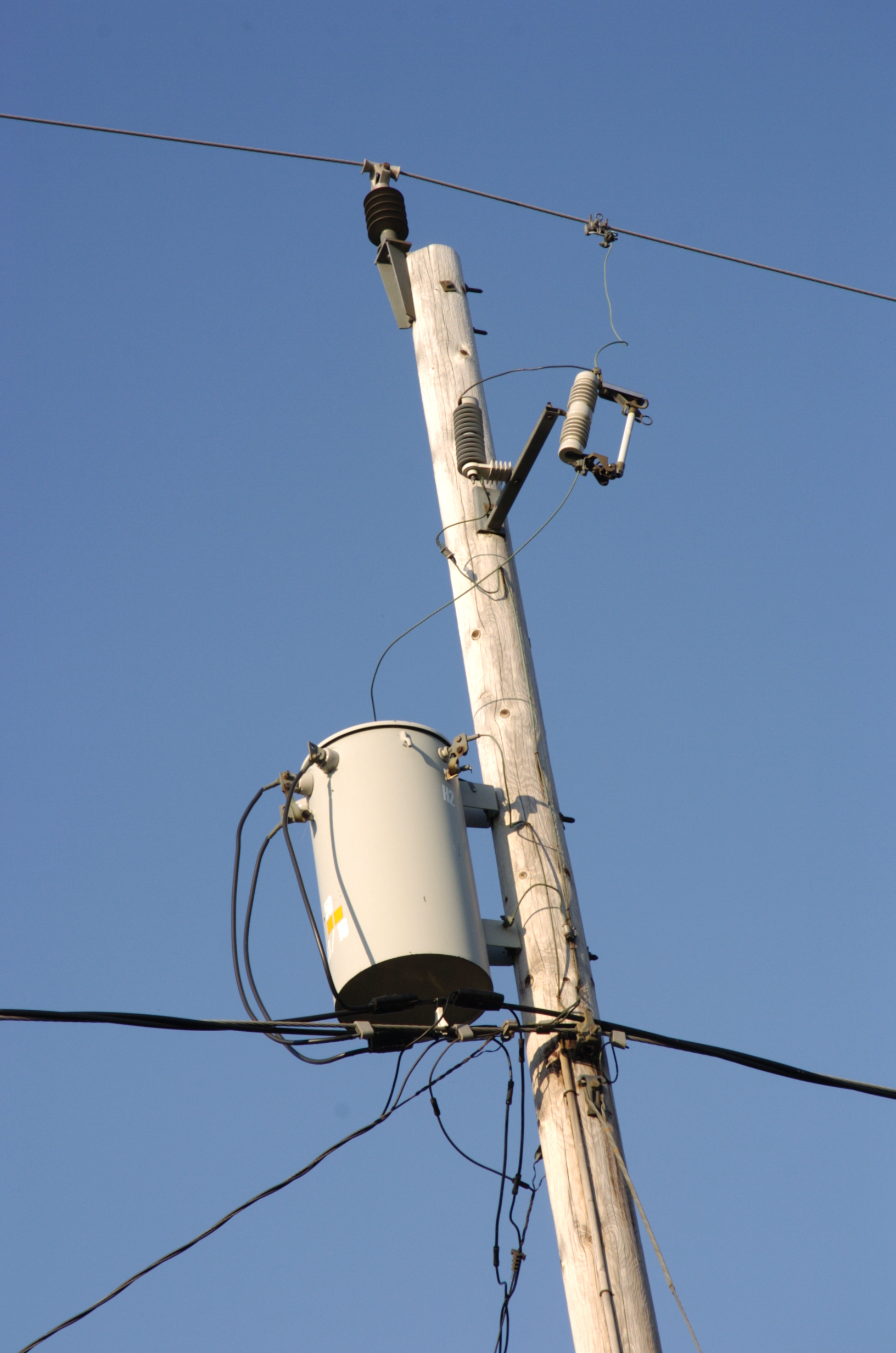
I added the image from the transformer artical because it is a split phase SWER transformer. It would be interesting to know where this was taken, if in the USA then SWER lines are being installed in the USA and the exception metioned in the SWER article are happening Charles Esson.
- The photo details say it was taken in Canada. —Preceding unsigned comment added by 61.9.139.165 (talk • contribs) 20:48, 16 July 2006 (UTC)
- Actually it says "about 12 miles from Dunville Ontario" (which is presumablly a misspelling of Dunnville, Ontario), our article does not however give enough information on dunvilles location to categorically place the picture in canda. Plugwash 14:19, 18 July 2006 (UTC)
- Single bushing transformers are used all over the place and so this does not mean this is an SWER installation. We can't see the overhead wires - could easily have a neutral conductor overhead. There is no point within 20 km of Dunnville Ontario that is part of the US according to Google Map. --Wtshymanski 17:51, 18 July 2006 (UTC)
- looking at http://wearcam.org/christina/billru_cottage/d325.jpg which appears to be a larger view of the photo in the article and some of the related images on http://wearcam.org/christina/billru_cottage/polemount.htm it looks like the horizontal wire in the picture is a neutral of some kind with the phase wire being higher up on the pole. Plugwash 23:47, 18 July 2006 (UTC)
Yes I see your point.--Charles Esson.
SWER systems, diagrams and an edit.
Editing notes
Sorry started out small and grew, hope you like the diagrams.
Removed 11KV from diagram, the primary voltage varies.
Created an image suitable for an international audience, as was image was obviously scanned from a book.
Neutral is always grounded, as written one gets the impression that the center tap is called neutral and the neutral may be grounded.
You can call the live conductors the ungrounded conductors, in the industry we refer them to as live, ungrounded may be clearer.
Changed the wording of the European example so it flowed on from the first, better for an international market.
Added the a reference to SWER lines ( my initial intent before I got carried away).
Removed the comment "The neutral conductor ensures that the voltages on the two legs do not get (far) out of balance". Doesn't belong in the paragraph covered better elsewhere.
Tried to internationalize the load comment.
Don't know where the 1/4 comes from, I could be wrong but I don't think I am. Diagrams created to make it clear in my mind. Could add another showing how the out of phase current subtract in the neutral conductor, oh well getting late.
The amount of copper is all about the total current carried.
Removed following; we are talking about copper not cost, why confuse the issue. "Furthermore, since smaller wires have higher costs per unit of area for insulation and installation labour, the costs won't go down by as much as the copper use, but the cost savings can still be significant."
Removed following; absolutely true but has little to do with this. "Voltage drop is generally the determining factor in cable sizing for long runs (whereas for short runs it is the cables current-carrying capacity rating)." --Charles Esson 13:33, 15 July 2006 (UTC)
- The primary reason for caring about copper use is the cost of the copper (which is one of the largest components of the cost of a cable) but it is not the only cost and more seperate cores means more insulation, more complex processing etc.—Preceding unsigned comment added by Plugwash (talk • contribs) 14:31, 15 July 2006 (UTC)
- What a great system, the reason for the 1/4 is now quite clear, thanks. Charles Esson
- If you double the voltage, you reduce the current to half to maintain the same power. So if you start at 240 volts and 200 amps, and change the voltage to 480 volts, now you only have 100 amps of current. That half current will now have a voltage drop across the fixed resistance of the same wire of half as many volts. If the voltage drop on the wire running some distance to feed a building from the transformer, when operating at 200 amps, is 4 volts, then at just 100 amps, that drop in voltage is only 2 volts. That means a transformer load in the building would be getting 236 volts in one case, or 478 volts in the other case. Reducing the 480 volt setup to a 240 volt setup with that transformer, you now get 239 volts (3 volts more than the 236 volts the other way). So doubling the voltage reduces the voltage drop to 1/4 as much, given a constant wire size. Typically, the wire size will be reduced to 1/2 the cross section, but that still reduces the voltage drop to 1/2 of what it would be at the lower voltage. Alternatively, the wire could be run a longer distance. Now consider the advantage gained by running the street distribution wires at 30 to 100 times the voltage. Skapare 02:01, 27 September 2006 (UTC)
German power distribution grid - for those who are interested!
As I live in Germany and deal with electric installations (project-planning of distribution-systems, installing switches, circuitbreakers of mid and heavy duty, surge-protection devices, ...) I know our distribution and its advantages and disadvantages very well.
First: We use 16 2/3 (for railways) and 50 Hz (standardgrid) the following voltage-levels to transport and distribute the energy:
Transport grid: Supergrid voltage: 220kV and 380/400kV 3-phase without neutral Highvoltage: 110kv (years ago 220kV was defined as "high voltage") 3-phase without neutral Highvoltage: 110kV for railways with 16 2/3 Hz 1-phase
Distribution grid: as above, and: 20kV 50Hz 3-phase without neutral 15kV 16 2/3 Hz 1-phase for railways 10kV 50Hz 3-phase without neutral 1kV 50Hz 3-phase 600/800V DC 1-phase for public transports (tube, ...) 230/400V 50Hz 3-phase 127/220V 50Hz 3-phase without neutral There are even more voltage levels as we have some old and very different types of distribution grids, if you like, I´ll write about it later!
We mainly use the 3-phase rotary-current system. This is a very efficient way to distribute power, especially for distances less than 500 kilometers. As 3-phase-transformers represent an equal load between the phases and the neutral point, they don´t need a neutral-point-connection. But as the transport-form is equilateral triangle (means the generator-connections are between L1-L2, L2-L3, L3-L1 (The phases) and the transformers are connection in the same way), we can also connect 1-phase-transformers. We have only three wires in the standard (not railway) transport and distribution ne (excluding the low-voltage level): The three Phases. Wie don´t need any N-Connection here. First at the mid-voltage-transformer-stations we change from three to four or five wires by connecting the 4th wire to the neutral-point of the secondary terminal. Our standard net-configuration in the low-voltage-level is TN (means: the neutral-point in the station is earthed, protection earth and neutral are combined in the Station and splitted at the consumer´s houses). TT (means: Neutral is earthed in the station but is explicitly declares as neutral - so it can be switched with the phases in other distribution cabinets between consumer house and station - know, it is strictly forbidden th switch a protection earth. In the consumer´s house the consumer gets his protection earth (PE) from his earth-installation which consists of metal sticks rammed into the ground) is used in some regions but mainly in the higher voltage levels from 10kV to 400kV.
We call the phases L1, L2 and L3, we call the neutral N, the protection earth PE and the combined neutral/earth PEN. The phases are, relating to a 360° circle, 120°-shifted, so there is a time delay: only between ONE time a currend can flow between N and ONE phase. It´s much to fast to see it with your eyes (150 times per second), but because this, one N is enough (unless the current that flows has much and heavy harmonic content).
We have 400 volts between L1 and L2, L2 and L3, L3 and L1. And we have 230 volts between L1 and N, L2 and N, L3 and N. This is a big advantage becaus we have a strong, motor-friendly possibility to connect strong consumer load and besides this a moderate possibility for small and mid-size consumers. We can handle heavy load with this system and the voltage-drop is low. An example: In the most german regions, You can attach load up to 45000W to the electrical system of a normal single house. Therefor we have three fuses (gl DIAZED or NH-system) in the main connection cabinet with 63 amps per fuse. As the gl-fuses react very slow and have high tolerances, you can even attach load up to 68000W for a certain time. In some houses (single fam) you can attach nominal 24000W, in three-fam often nominal loads up to 70000W or even more.
Although we also have old and dangerous installations, we have a very high standard in distribution of electrical energy. If someone is interested in pictures, let me know. And ask if you have questions!
sincerely, Alex —Preceding unsigned comment added by 84.174.248.49 (talk • contribs) 09:26, 16 August 2007 (UTC)
As with three phase?
"Houses in the UK normally only have single ended single phase power and so (as with three phase) only one active line and the neutral is taken to each house." As with three phase? what does this mean? --Gbleem 04:32, 2 September 2006 (UTC)
- It means the same as when the cables in the street are three phase. Plugwash 17:22, 3 September 2006 (UTC)
- I believe it means that in some places only 2 of the 3 phases are available on the street, and in other places all 3 phases are available. Larger homes that need a 240/415 volt supply may be typically provided with only 2 of the 3 phases, since there is very little real three phase need in a home. But a large electric stove may be designed to run on 415 volts to help keep the wires from having to be too large. The utility can cut costs by running only 2 phases on each street and connecting just 2 single phase transformers to provide the 240/415. The ratio of the voltages is the square root of 3 (approximately 1.732050807568877), not 2 as in the true single phase split system. Skapare 02:25, 27 September 2006 (UTC)
- You're guessing. Generally, anything that requires 415 volts is a 3-phase load. Now having said that, I'm sure someone will provide an example of a 415 volt single phase appliance. 86.176.152.185 (talk) 13:40, 11 February 2011 (UTC)
- Many 415 V loads are 3-phase. Because of the improved performance of 3-phase motors, and 3-phase rectifiers, there are good reasons for preferring 3 phase power for many loads. However, 415 V single phase loads are, nevertheless, common for cases where the load is sufficiently large that it benefits from the reduced load-related voltage drop of the higher supply voltage and lower cabling costs due to lower currents, but the other advantages of 3 phase are not relevant. Such loads would be connected between any 2 phases. For example large building-site transformers (for producing 55-0-55 110V electricity) are often powered from 415 V, yet are a single phase load. Similarly, medium power non-motorized industrial equipment may be powered from 415 V single phase (e.g. high power flood lighting, light duty X-ray equipment, space heating, etc.)ChumpusRex (talk) 17:11, 22 May 2011 (UTC)
230 V / 240 V
IMO we should change references to 240 V / 480 V to 230 V / 460 V in respect of European systems where the nominal voltage is 230 V. Anybody disagree? --Ali@gwc.org.uk 21:35, 16 October 2005 (UTC)
- Go ahead if you wan't i don't have any particularlly strong feelings either way on this. Plugwash 00:59, 17 October 2005 (UTC)
Where the reference specifically is about what is in Europe, then of course 230 volts should be the voltage referred to since that is now the official standard (plus or minus 10 volts). But for split phase in general, the competing references would be to use either 120/240 as in the US and Canada, or 100/200 as in Japan, where this split phase system is dominant. When you do have a 3 wire circuit like this, the correct way to reference the voltage is with 2 numbers, e.g. 120/240. That's much like three phase, except it is common, though not exclusive, to put the lower voltage first. Three phase would almost always put the larger number first (and North Americans include "Y" in reference to Wye), e.g. 208/120 (US, Canada), 220/127 (Mexico), 380/220 (much of the world), 400/230 (Europe and much of the world), 415/240 (Much of the former British Empire), 480/277 (US commercial and industrial), 600/347 (Canada commercial and industrial), 690/400 (Europe industrial), and 1000/577 (US mines).
By the way, the reference in the article about using just 2 wires to get one voltage out of a dual voltage split phase system, e.g. getting just 230 volts from a 230/460 volt center tapped transformer, as being cheaper, is not really correct. If you happen to have the split phase system available, it is actually cheaper to go with three wires, assuming wire assemblies being equally available. The reason this is so is because you would only need half the current capacity. If you needed 100 amps of 230 volt power, that would require 2 wires that have 100 amp capacity in both, or 3 wires that have only 50 amp capacity in all three. The latter is a lesser total cross section of wire. The fundamental reason is because in part, the voltage is effectively higher (e.g. 460 volts). Perhaps the comfusion comes from comparing the European single phase system (2 wires, 100 amps each, just 230 volts) to the North American single phase system (3 wires, 100 amps each, dual 120/240 volts). The European system is the wiring cost winner when comparing the same amperage as the same maximum voltage. But if there is a 230/460 volt transformer there, then going with a 3-wire split phase system saves even more over both the 2-wire 230 volt system and the 3-wire 120/240 volt system because the wires can now be thinner. And 460 volts doesn't require much more in insulation nor is it much more dangerous (it's still 230 volts relative to ground). The North American 120/240 volt system can be, and is, used at 240 volts for many things, but is actually a bit safer for grounded contact because the voltage is not more than 120 volts relative to ground. It's only when one contacts both of the opposite "phase" wires that the higher voltage is involved. Skapare 01:37, 27 September 2006 (UTC)
- To clarify this: the actual European mains voltage is not 230 volts. No European country has an actual mains voltage of 230 volts. The UK is still 240 volts (with a few pockets of resistance at 250 volts - particualrly the suburbs of larger cities). Practically all of mainland Europe is 220 volts. What has happened is that the voltage tolerances have been relaxed and has been declared to be nominally 230 volts plus or minus 10%. Most appliances are required to operate within this voltage band. The band actually covers 207 to 253 volts so the whole of the European Union complies even though individual actual voltages may vary. Some voltage sensitive items, such as filament lamps, are still rated at 220 volts in mainland Europe and 240 volts in the UK. 86.176.152.185 (talk) 13:26, 11 February 2011 (UTC)
No, Central Europa has 230 volts, from Espaina to Poland and from Norway to Italy Europa is switch to getter in one system. May by UK has 240 volts minus 10 volts minus 5%. The tolerances in Europa is less then 5% in Central Europa, that mens from 218,5 volts to 241,5 volts. Europa usaly did not have split-phase, usaly every haus or farm has "Drehstrom", 3 hot Phase with 230 volts to ground and 400 volts circular between them. 79.230.165.79 (talk) 00:45, 15 May 2011 (UTC)
- No: central Europe is nominally 230 volt. Get your voltmeter out and measure it. You will find that it is nearer to 220 volts than 230 volts. 86.182.103.115 (talk) 16:01, 9 June 2011 (UTC)
- And the relevance to this article is? A 240 V distribution system that measures 230 V is already heavily loaded and is on the edge of passing out of the allowable voltage range. --Wtshymanski (talk)
- And loading has precisely what to with my point? The lower end of the tolerance range is now way below 230 volts at 207 volts, so it wouldn't even be close to passing out of the allowable range (since 2008). 86.182.103.115 (talk) 15:43, 10 June 2011 (UTC)
- Sigh. More precisely, if you are a North American utility, you intend to serve your customers within the ranges specified in ANSI C84.1 Range A, which is -5% to +5% at the service entrance for a 120/240 V service. If the service entrance voltage is as low as 230 volts at the service entrance, you've already used up 4%, leaving very little for voltage drop in the wiring. 120/240 split phase systems tend to be used in areas where ANSI C84.1 is the standard. (Range B allows momentary -10%, +6% but immediate corrective action is supposed to be taken to get back in Range A - 207 volts is well outside Range B for a 240 volt service (13% low) and would be considered out of tolerance for a service entrance. European practice seems to vary widely and none of our many European contributors have seen fit to quote the actual standards and allowed ranges. I'm sure European utilities have standards taht are a lot tighter than -20%, +20%. --Wtshymanski (talk) 16:12, 10 June 2011 (UTC)
- And loading has precisely what to with my point? The lower end of the tolerance range is now way below 230 volts at 207 volts, so it wouldn't even be close to passing out of the allowable range (since 2008). 86.182.103.115 (talk) 15:43, 10 June 2011 (UTC)
- 240/480 is three wire, three phase (hot wire) rotating 120 degree. 240/480 has only tow hot wire with oposit 180 degree.
( someone from germany)
Wild-leg diagram erroneous?
I'm not knowledgeable in this subject, but it seems like "neutral" should be placed at the origin in the "wild-leg" diagram. (Or rather, the origin ought to be placed at "neutral"; since the placement of neutral as given is correct with respect to the phases.) If that is not the case, what is the constraint that determines where it is placed? User:Glenn Willen (Talk) 07:58, 7 February 2012 (UTC)
- I avoid editing articles in which I'm not knowledeable on the subject, as I get my kniuckles rapped regularly when I try. There's nothing to connect to at the "origin", the drawing is not great and should emphasize actual transformer windings. --Wtshymanski (talk) 14:27, 7 February 2012 (UTC)
Used in Europe?
In the UK and Europe 230/460 V, 3-wire, single-phase systems are used to run farms and small groups of houses when only two of the three phase high voltage conductors are available (it is cheaper to run two wires than three). I dont know a motor or somethink other for 460V. Common is a 3 phase system with 2 voltages. For ex. 230/400V.—Preceding unsigned comment added by 80.109.73.21 (talk • contribs) 22:40, 23 August 2006 (UTC)
- Its not used anywhere near as much here as 3 phase is but it certainly is arround (its generally used where they wan't to supply more than they think they can handle as single ended single phase but they don't wan't to bother with 3 phase MV stuff). As the article says though its pretty much unheared of to use 460V for anything and its normally split out into single ended single phase either before or as soon as it reaches the customer. Plugwash 01:13, 24 August 2006 (UTC)
- It's not used in UK at all. 60+ years ago, it was used for a very small number of outlying farm supplies, where the 480V was used for heavy loads in the absence of 3-phase. Farms all have 3-phase available nowadays if they need it. I can't comment on the rest of Europe, except to say I've never seen it, but the reference to the UK should definitely be removed. 81.187.162.109 (talk) 09:19, 6 February 2010 (UTC)
- Split-phase installations in the UK are few, but do exist (and often cause huge confusion among electrical contractors and customers, as in 2010, most electricians will not have seen one), where they were initially installed in the immediately post-WW2 period. For new supply, 3 phase is standard where power demands exceed that of a single phase. Split phase, in very exceptional cases, is still available for a 'new' customer - but this would only be where a split-phase supplied site is redeveloped (e.g. a rural farm has added new buildings), but where an upgrade to 3 phase would not be economically justifiable. (e.g. where the upgrade would involve upgrading many miles of 11,000 volt overhead poles from 2-wire to 3-wire). ChumpusRex (talk) 21:03, 28 May 2010 (UTC)
- Actually, you are wrong. A few experimental installations in West London (and I believe a few other places) were installed as 230 volt systems wired as 115-0-115 volt. There was no intention of any consumer actually running 115 volt appliances, the system was purely so that the maximum voltage to earth was 115 volts. The system was not considered to offer enough advantage to be adopted universally. Although it never spread, in those areas where it was installed, it is still in use.
- Having said that, the basic idea was adopted throughout most of Europe for portable electric tools for use on building sites etc. These are designed to operate from 110 volts and are powered from a transformer with a 55-0-55 volt secondary. With the centre tap earthed, the maximum voltage to earth is just 55 volts. 86.176.152.185 (talk) 13:37, 11 February 2011 (UTC)
- There are still a good few such systems in use in rural Norfolk. Here's a typical installation:
https://maps.google.co.uk/?ll=52.79586,1.479678&spn=0.007318,0.013175&t=m&z=16&layer=c&cbll=52.795758,1.475258&panoid=ZscRfho5ilJMvLya0IspsQ&cbp=12,354.35,,0,-1.23 80.189.79.87 (talk) 09:24, 22 May 2014 (UTC)
- Dont know abaut UK, but in Europa with out UK Split-Power is not knwon. Heer always used 3 phase hot wire and earth. That meens 3x 230 V oder 400 V (old 220V 380 V). UK use 240/460 or 230/400V with three hot wire.
But UK Elektrik is differnt. (someone from germany) — Preceding unsigned comment added by 212.9.60.124 (talk) 08:04, 14 April 2014 (UTC)
Split Single Phase vs. Two Phases from Wye
As we know, North American split phase systems universally assume double the phase voltage between the hot legs, and appliances are designed around that fact. Say, if it was a water heater, it would have a single heating element rated for 240 V.
How ever (as I have understood) some other places, namely Japan, don't make that assumption. Their NEMA 14-30 could be both way, it could be fed from a center tapped single phase transformer or from three phase Y. Thus, a Japanese water heater would have two elements both rated for 100 V.
Correct?
I come from Europe, so I have never actually seen systems other than 400/230 V ΔY.
--80.221.56.194 (talk) 10:12, 15 February 2015 (UTC)
- What's more, one could wire an induction motor to run from such a "two phase" service. This is the sole reference I have, having read "somewhere" that this could happen in Japan, that small workshops for example could opt for two pahases in 100 V and connect it to just the two of the tree terminals in a motor, which then would smoothly and balancedly run just like a regular 175/100 V three phase motor in Y configuration from their perspective; the horrible power inbalance would ofcourse remain in the supply side. What I am certain about is that the Japanese usually use 200 V Δ for lage motor loads.
- -- The same guy 87.92.152.118 (talk) 18:51, 31 March 2015 (UTC)
Alleged error
There is an error. In Europe we have 3-phase system where 1 phase has 230V 50Hz, and phase to phase voltage is 400V(3ph 120°) not 460V(2phase 180°). —Preceding unsigned comment added by 194.169.228.3 (talk • contribs) 23:11, 18 June 2008 (UTC)
- We don't give much weight to unsigned, out-of-context comments by anonymous editors incompetently placed in random locations on Talk pages. —QuicksilverT @ 03:18, 6 October 2010 (UTC)
- That's very uncivil. 69.221.162.31 (talk) 10:41, 31 December 2010 (UTC)
- They don't use this much if at all in the EU, that's for sure. In contract, 460/230V 50 Hz split phase from SWER high voltage feed is somewhat common in Australia and New Zealand, so it is a thing and having the diagram list both 120/240V and 230/460V is valid.
- --80.221.56.194 (talk) 10:43, 15 February 2015 (UTC)
-- a error : tracktion power for railway the power for railway is not split-power-three-wire. Highvoltage siede is 110 000 Volt single ac with two wire. mostly 4 wire 2 ac. than transform to 15 000 Volt single wire other side earth by railway. booth with 16 3/4 Hz (or now 16.6 Hz) . Tram and lokal Raylway have differtn Volt ac or dc. 212.9.60.124 (talk) 08:22, 14 April 2014 (UTC)
- There are both ways around the world. There's one sided system with cored isolation transformers every few miles to keep the stray currents in check and there is also the two sided system which uses autotransformers with center-tap connected to the rails for the same effect with added benefit of doubling the effective transmission voltage.
- --80.221.56.194 (talk) 10:39, 15 February 2015 (UTC)
Yes, exactly as in the UK at present. The single sided feed with booster transformers (really common-mode chokes) every few miles was universal in the UK until recently, but now they are going to the autotransformers with centre tap connected to the traction return rail as you say (the other rail is used for train detection for the signalling system). Double the overall voltage means less loss. Tiger99 (talk) 15:57, 18 July 2015 (UTC)
UK portable tool transformers
The portable yellow tool transformers used on construction sites in the UK are not isolation transformers. They provide 110V through a split phase secondary (two conductors at 55V and 180 degrees out of phase) with a centre tapped earth and no neutral. — Preceding unsigned comment added by 82.45.93.135 (talk) 04:03, 25 December 2016 (UTC)
Technical power (balanced power)
The "Technical power (balanced power)" section is currently tagged as "The examples and perspective in this section may not represent a worldwide view of the subject." The section says specifies that it is based on "The U.S. National Electrical Code" and does not claim to be universal. It seems to me that either the tag should be removed or it should be attached to all the other non-universal information in the article as well. — Preceding unsigned comment added by 199.19.94.135 (talk) 16:55, 7 October 2016 (UTC)
- I think the problem is that split phase is only widely used as a standard method of power distribution in 110V countries like the US, so the whole article comes across as US centric with a few token references to niche applications elsewhere. Maybe the best solution is to rewrite the article to make this US focus explicit. There's nothing wrong with having an article about a US system of power distribution so long as it doesn't pretend to be global. --Ef80 (talk) 16:23, 16 June 2017 (UTC)
- Centre-tapped transformers are common world-wide. My power here in the UK is provided by a transformer with a 500v secondary with earthed centre-tap. Dbfirs 16:45, 16 June 2017 (UTC)
- You may indeed have such an arrangement, but it is certainly not common in Britain apart from for the odd farm in the middle of nowhere. The article itself correctly states this. --Ef80 (talk) 21:24, 16 June 2017 (UTC)
- I agree that it's not common in towns and cities, but a small proportion of the British population lives in the countryside where this arrangement is common. The article correctly states this. Dbfirs 22:53, 16 June 2017 (UTC)
- You may indeed have such an arrangement, but it is certainly not common in Britain apart from for the odd farm in the middle of nowhere. The article itself correctly states this. --Ef80 (talk) 21:24, 16 June 2017 (UTC)
- Centre-tapped transformers are common world-wide. My power here in the UK is provided by a transformer with a 500v secondary with earthed centre-tap. Dbfirs 16:45, 16 June 2017 (UTC)
Split phase is (not) two phases
In my opinion split phase should also be called 2 phase because we create and utilize two voltage signals with respect to ground. These two voltage signals are out of phase by 180 degrees with respect to ground. The Thevenin equivalent voltage source must be defined as: L1 to N = 120V @ 0 degrees and L2 to N = 120V @ 180 degrees (or vice versa)
One could argue that L1 to N and N to L2 are in phase. But this would require a negative vector which is the same as a positive vector @ 180 degrees. Or it would require the definition of ground = zero volts to be void.—Preceding unsigned comment added by 24.59.27.8 (talk • contribs) 04:12, 23 March 2006 (UTC)

- Two-phase electric power has two sinewaves 90 degrees apart, and is normally a four-wire system. Split-phase has two sine waves 180 degrees apart which can be summed together, and is supplied as a two-wire system.
- Two-phase is obsolete and was only used in the late 1800's and early 1900's before fading out, replaced by the more efficient three-phase that only needs 3 wires to carry the three phases. DMahalko (talk) 09:51, 16 May 2008 (UTC)
- Unfortunately, by convention, it isn't named that way. While a computer engineer might speak of a "two phase clock" that operates exactly this way (two signals 180° out of phase), power engineers don't use this terminology. To them, it's only two-phase if the two phase legs are 90° out of phase. It's not necessarily logical, just the (universal) convention among the power engineering cognoscenti. --Atlant 15:33, 23 March 2006 (UTC)
- It's only 2-phase if you can start an induction motor off it, without messing about with starting windings, capacitors, etc. - a very pragmatic definition. If it doesn't make a revolving magnetic field, it's not polyphase. --Wtshymanski 18:33, 23 March 2006 (UTC)
- Actually the two windings on the secondary side are in phase and not out by 180°. If you go from the bottom of either winding (in the diagram) to the top of that same winding you get V @ 0°. It is only when you start at the N wire in the middle and go in opposite directions that it appears out of phase. In industrial settings it is very common to use transformers that are not just tapped in the center but provide two wires per secondary winding. This allows series or parallel connections.—Preceding unsigned comment added by Crunchy Numbers (talk • contribs) 18:36, 30 August 2006 (UTC)
- The two windings are generally just one winding, anyway. It's around one core. Whereas in three phase power, the windings are separated to 3 legs of an "E" core, or 3 separate cores are used. Many "split phase" transformers actually have 2 separate windings with a total of 4 wires. They can be wired in series using the common point as a neutral as described by the article, or the 2 windings can be wired parallel to get the half voltage at double the amperage.
You can use the term "poles" in reference to the number of different phase vectors out from the neutral center point. This is what typical electricians and power engineers often use. Skapare 01:43, 27 September 2006 (UTC)
- The two windings are generally just one winding, anyway. It's around one core. Whereas in three phase power, the windings are separated to 3 legs of an "E" core, or 3 separate cores are used. Many "split phase" transformers actually have 2 separate windings with a total of 4 wires. They can be wired in series using the common point as a neutral as described by the article, or the 2 windings can be wired parallel to get the half voltage at double the amperage.
- The proper engineering term for the two outputs of a center-neutral split phase transformer is "legs", not "phases" or "poles". Correction made to article accordingly. This should help dispel reader confusion.—QuicksilverT @ 00:46, 6 October 2010 (UTC)
- What is truly silly is that the "electrical" industry talks about a "neutral" (white) wire as if it never carries current, and is designed to carry almost none. But that is true ONLY in a well-balanced system, which is almost never true in real life. And there is nothing that prevents someone from loading only one "leg" of a 120vac split phase system (apart from panel design, of course). In that case, of course, the neutral would carry exactly as much current as the "hot" leg. The electrons don't care which direction they are traveling. There is some strange bias in the AC world that wants to treat the so-called Neutral conductor as a DC Ground. And it isn't a ground wire at all. It is shunted to the earth in some systems for safety, but that's not the same as a DC 0 volt ground. Personally, I think most electricians have a very poor understanding of electron flow and what's really happening in the systems they work on. It's just too complex for someone to master in a trade school and high school education (or less). I've only hired a couple of electricians, and they usually don't know what a phase angle with regard to a sine wave actually means. That's scary. And I usually have to go back and re-wire their shoddy work to avoid having my house burn down. This is why Edison preferred DC. With his lack of education, he simply couldn't get his head around the AC complexities. 98.194.39.86 (talk) 04:36, 28 July 2017 (UTC)
- "It's only 2-phase if you can start an induction motor off it" - is not an adequate way to describe a system's design. That's the rough equivalent of saying: "It's only a high voltage if it shocks you enough to leave a mark." Seriously. 98.194.39.86 (talk) 04:46, 28 July 2017 (UTC)
I don't get it
from the article:
A transformer connected to a 3-wire distribution system has a single phase input (primary) winding. The output (secondary) winding is centre-tapped with a conductor called the neutral on the centre tap, which is normally connected to earth ground
I don't understand this part. May someone give another explanation or draw a picture? Great! --Abdull 13:01, 23 July 2005 (UTC)
- Abdul, I need to establish a baseline here: Do you understand the concept of a transformer (say, a "filament transformer") that has an ordinary line-voltage primary and a centre-tapped low voltage secondary? —Atlant 00:10, 24 July 2005 (UTC)
These explanations or dingly. They don't complete the thought. They just dingle in the air. Abdul,,,,you did not do your job. Explain what is going on here...or I will have to. — Preceding unsigned comment added by Longinus876 (talk • contribs) 15:53, 15 December 2017 (UTC)
Where does the "second" phase offset come from?
If I understand this correctly, the transformer is supplied to the primary winding with a single phase, higher voltage, and the secondary is tapped on both ends, giving 2 120V lines. What I dont understand is how these two lines are out of phase with each other. Or are they? I always assumed that you couldnt get a difference in potential between two 120V AC lines unless they were 90° out of phase with each other.—Preceding unsigned comment added by Dirkaboo (talk • contribs) 22:12, 4 August 2005 (UTC)
- With split phase they are 180° out of phase. That is they are the exact inverse of each other. Therefore they can be obtained from the centre tapped secondry winding of a single phase transformer. —Preceding unsigned comment added by Plugwash (talk • contribs) 22:44, 4 August 2005 (UTC)
- The question remains, How are they 180 degrees out of phase? The answer is simple: If you imagine the transformer standing vertically, the first phase is established by making the hot tap at the top of the transformer and making the neutral tap at the middle. Now if the second phase was established by taking the "hot" tap at the middle and the "neutral" tap at the bottom you would have two identical phases. But, note that the technique is to establish the second phase by making the hot tap at the bottom and the neutral tap in the middle, the same location of the neutral in the first phase. This creates a mirror image of the first phase (i.e. upsidedown). To prove this you may connect the second phase to an occiliscope twice. Once correctly connecting the hot and neutral to the scope, and once connecting them backward. You will see the phase flip. —Preceding unsigned comment added by Canavair (talk • contribs) 15:28, 13 September 2006 (UTC)
- "To prove this you may connect the second phase to an occiliscope twice. Once correctly connecting the hot and neutral to the scope, and once connecting them backward. You will see the phase flip." <-- I consider this a dangerous suggestion. The chances of someone thinking of trying this having isolated scope probes suitable for mains is near zero IMO. Plugwash (talk) 21:18, 10 March 2009 (UTC)
- Part of your confusion, user Dirkaboo, is due to the misuse of the term "phase". The outputs of a transformer secondary in a single split-phase system are properly called "legs", not "phases". I've corrected the article to reflect this. —QuicksilverT @ 00:40, 6 October 2010 (UTC)
Want a clear answer? The secondary alternates plus and minus on the wires that are the outputs. Like a seesaw. Do you know a seesaw or is it a teeter totter? The kids sit on them and go up and down. Got it? If you look at the middle, it doesn't go up and down. It stays at one height. It's "neutral". It's height is in the middle of either end of the seesaw. Either end will be so many feet above the other. But the center will only be half of that. Think.... The secondary is exactly the same. One end of the secondary is up while the other end is down. But the center-tap stays the same. It never moves. It's "neutral" Voltage is always the difference between the high and the low potential. That's why we call the center tap neutral. It's in the middle and we try to keep it there. So any measurement from the end of the seesaw to the center is always going to be half the distance to the other end. I hope that makes sense. Longinus876 (talk) 16:45, 15 December 2017 (UTC)
Tesla?
How is it that any definition of split-phase induction makes no mention of Tesla?—Preceding unsigned comment added by 69.249.133.182 (talk • contribs) 00:40, 5 May 2010 (UTC)
- As far as I can tell from a quick online search, Nikola Tesla helped develop polyphase induction motors, not split-phase? -- Beland (talk) 05:05, 1 May 2018 (UTC)
Water *pumps* are connected across two line conductors?
"Large appliances, such as cooking equipment, space heating, water pumps, clothes dryers, and air conditioners are connected across the two line conductors, requiring less current and smaller conductors than would be needed if the appliances were designed for the lower voltage. [2]"
I can only speak for the U.S., and I don't have access to the cited source, but the only water pumps in a household would be referred to in Wiki-speak as WELL pumps, and they're typically found only in rural locales. Further, "water heaters", which are a common household use of line-to-line power in the U.S., are omitted. Therefore I believe that this was supposed to be worded as
"Large appliances, such as cooking equipment, space heating, water heaters, clothes dryers, and air conditioners are connected across the two line conductors, requiring less current and smaller conductors than would be needed if the appliances were designed for the lower voltage. [2]" Sbrasel (talk) 00:48, 21 June 2018 (UTC)
- Yes, I think that would be an improvement to the article. Just go ahead and make the change. We don't use split-phase in this way in the UK, so I can't comment of what someone intended by "water pumps". Dbfirs 07:01, 21 June 2018 (UTC)
Misnomer
I think split-phase is a misnomer in this context. I would say split potential because we are splitting the voltage, not the phase. Split-phase is a means of producing two-phase current from single phase for running induction motors. See split-phase motor. Roberttherambler (talk) 15:09, 22 August 2017 (UTC)
- See WP:COMMONNAME. Andy Dingley (talk) 15:19, 22 August 2017 (UTC)
- But is it a common name? I have never heard the single-phase three-wire system described as "split phase", except in Wikipedia. Roberttherambler (talk) 15:44, 22 August 2017 (UTC)
- OK, there are plenty of hits for it on the internet. I think it's an American term which is not used in England. Roberttherambler (talk) 15:51, 22 August 2017 (UTC)
- Yes, but that's because we don't wire much this way, not because we call it something else. We have a small amount rurally, and that's called split-phase. Andy Dingley (talk) 16:19, 22 August 2017 (UTC)
- My electricity supply here in Cumbria (UK) comes as one half of a split phase. The local church has many space heaters and uses both halves of the split phase but on separate circuits. The phases are 180 degrees apart. I suppose you could call it "split potential" since the final centre-tapped transformer produces 500 volts (split into separate 250v supplies), but I've never heard it called that. Dbfirs 07:08, 21 June 2018 (UTC)
- Yes, but that's because we don't wire much this way, not because we call it something else. We have a small amount rurally, and that's called split-phase. Andy Dingley (talk) 16:19, 22 August 2017 (UTC)
- OK, there are plenty of hits for it on the internet. I think it's an American term which is not used in England. Roberttherambler (talk) 15:51, 22 August 2017 (UTC)
Phase diagram needed
This article could use a diagram that illustrates how 120VAC + 120VAC = 240VAC when they are out of phase 180°. -- Beland (talk) 05:58, 1 May 2018 (UTC)
The diagram should also illustrate a 120VAC/120VAC/208VAC configuration. Cycle0 (talk) 18:25, 11 July 2019 (UTC)
Quarter size or half size?
Currently it reads: "Longer wiring runs are more limited by voltage drop in the conductors. Because the supply voltage is doubled, a balanced load can tolerate double the voltage drop, allowing quarter-sized conductors to be used; this uses 3/8 the copper of an equivalent single-phase system."
I think that "half-sized conductors" is meant here as opposed to "quarter-sized". If (as claimed) the voltage drop per unit length can be twice as great in a split-phase system compared with an unsplit system then the cross-sectional area of the conductors used can be half (not a quarter) as great; and the diameter of the wire, if round, can be 1/√2 as great.
The figure of ½ multiplied by the earlier figure of ¾ yields the stated ⅜.
Or am I misunderstanding something? Jdthood (talk) 20:06, 16 August 2019 (UTC)
180 degrees out of phase
An editor has six times removed the statement about the two legs of a split-phase supply being 180 degrees out of phase. I'm trying to find out what he thinks is incorrect about this statement. Is there a better way to phrase the statement? Dbfirs 06:45, 10 September 2019 (UTC)